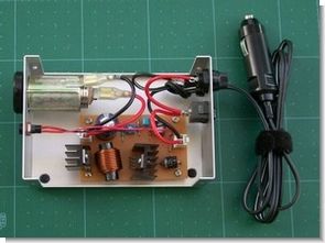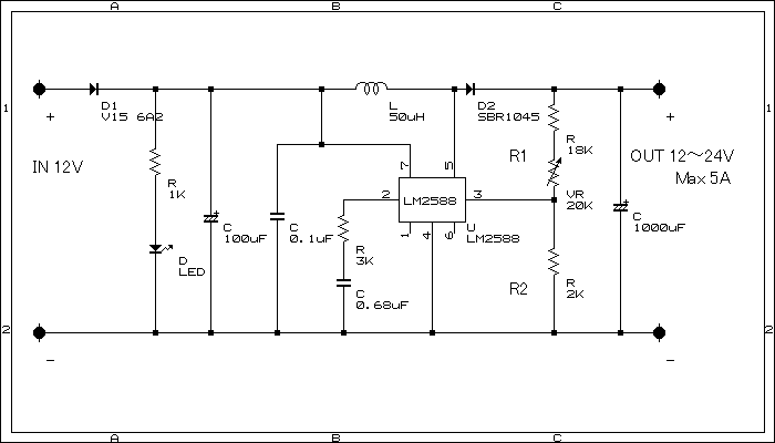
The input voltage is 12v, the output is adjustable between 12-24 volts. It has 5 ampere power. The coil used is 50μH 5 amps. Setting the LM2588-ADJ output voltage is determined by the resistance values of R1 and R2. Output can be adjusted by using a series or direct trimpot to the R1 resistor.
LM2588-ADJ output calculation;
V output = V REF (1 + R1 / R2)
VREF = 1.23
A 5A or higher power diode can be used, as diode D1 is a diode that protects the circuit when the + and – values of the input are reversed. Diode D2 is a Schottky barrier diode A 5A or higher power diode can be used.

LM2588ADJ 12V to 24V Step-up Schematic
Booster DC-DC converter LM2588-ADJ
parts list
Regulator IC LM2588-ADJ
Diodes D1: V15 6A2
D2: SBR1045 (Schottky barrier diode)
Capacitors 1000μF 50V
100μF 50V
0.1μF
0.68μF
Resistor 1KΩ, 2KΩ, 3KΩ, 18KΩ,
Pot or trimpot 20kΩ
Coil 50μH 5A
Cooler 2
Published: 2009/01/18 Tags: dc dc converter circuit, power electronic projects


PIC16F84 Multiple Programming Circuit
So far I have not seen such a circuit in a web environment could work in mass production programming section has been removed by the original photos used only copying part of an integrated control pic16c64 asm lib, etc. scr. There are resource files (.lzh extension, you can open files with WinRAR) with one source can be copied pic 8 18 volt dc supply voltage is regulated with 78xx series