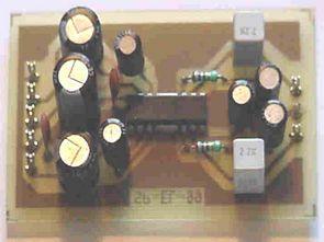
2 watts summer look that many computer users within the mini-500w sound system than the quality of integrated 2W Amplifier la4182’s 🙂 circuit can operate with supply voltages from 5v … 9v.
LA4182 2-Channel AF Power Amplifier
Built-in 2 channels enabling use in stereo and bridge amplifier applications. High output: 2.3 W/channel, VCC = 9 V, RL = 4 W, and 4.7 W/bridge, RL = 8 W. Minimum number of external parts required : 9 pcs. min. (Stereo/bridge). Small pop noise at the time of power supply ON/OFF due to built-in muting circuit. Good ripple rejection ratio due to built-in ripple filter. Soft tone at the time of output saturation. Good channel separation. . Voltage gain fixed at 45 dB (Bridge: 51 dB)
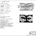
LA4182 Circuit diagram, pcb drawings:
Published: 2010/08/01 Tags: audio amplifier circuits, ic amplifier

Various RF Transceiver Circuits
Many printed circuit board with circuit diagrams circuit applied RF Transceivers list; Selective Amplifier circuit VHF, 433 MHz, 4-channel relay output receiver circuit, 433.92 MHz receiver module (ASK), AV modulator circuit, SAW resonator oscillator, Coded IR Wireless Transmitter 2 +1 channel
IR wireless receiver 4 +1 channel, 433.92 MHz RF coded key in the door, doorbell 433.92 MHz RF receiver 433.92 MHz RF transmitter 2 +1 channel, did VAHVIS RF-RF Amplifier RF Amplifier, Solar battery-powered FM transmitter, IR transmitter (uncoded), IR receiver (uncoded)
RF Transceiver Circuits