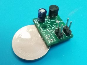
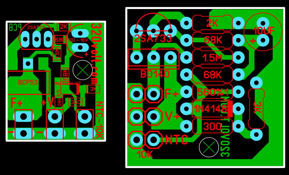
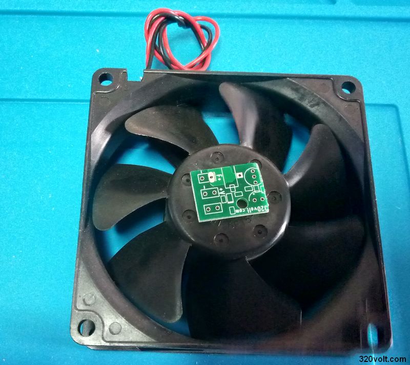
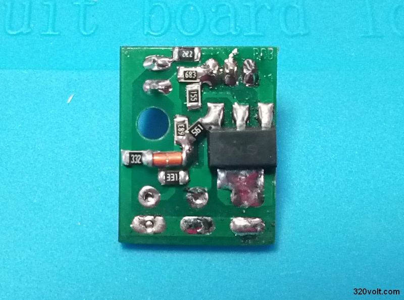
A circuit PCB design that adjusts the fan speed according to the temperature was made as small as possible, most of the components are SMD, in addition to the fan control circuit I share in the PCB drawing I prepared for DIP components.
Fan control circuit; Amplifier, power supply circuits etc. The fan control circuit, which can be used in many power applications requiring cooling, automatically increases the fan speed according to the cooler temperature. Thus, the fan is long-lasting and does not make a lot of noise unnecessarily full speed.
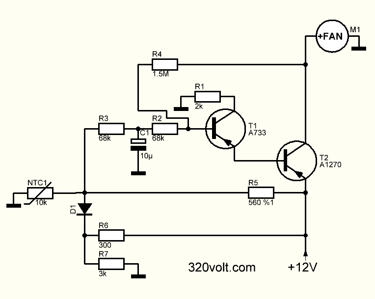
Actually, there were much simpler circuits, but we used this circuit because it was ready and we had no problems with our experiments. I copied the circuit from a quality ATX power supply, it is used in a few devices, in fact, a complete SMD design would be made, but this was more than enough.
All of the SMD resistors 805 sheath power transistor BCP53 NTC value used for SMD heat detection I used different values because I could not find some resistance values in the 10K original circuit, use the same values if possible
330-OHM instead of 300-OHM
3.3K instead of 3K
2.2K instead of 2K
I used 560-OHM 5% instead of 560-OHM 1% tolerance resistor
SMD design PCB size 14.4X17.5mm PCB drawing you see in the pictures had placement errors, I edited them. If the DIP version PCB size is 23.3X23.5mm DIP version was prepared for the article 🙂 I checked, I did not see any problem, but I did not try. I did not use the 6.8V 1W zener connected between the collector and the emitter of the power transistor in the original circuit, if I remember correctly, it kept the speed high at low temperature.
PCB drawings are prepared with Sprint layout 6, there are source drawing files.
NTC Fan Control Circuit Diagram
NTC Fan Speed Control Test Video
Şifre-Pass: 320volt.com
Publication date: 2021/01/12 Tags: analog circuits projects
What is the output power limit of this circuit?
Hi, I tested it with 120 mA and had no problems. It can deliver higher current according to transistor power