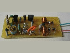
FM transmitter circuits are generally used for music broadcasting, but this circuit is a little different, you can listen to conversations on the set FM band by connecting the circuit in parallel to the telephone line. The FM transmitter circuit does not need an additional power source, it receives the energy required for its operation from the telephone line
There is a list of materials used in the circuit, coil winding information, and pcb drawings.
Note: Since the circuit broadcasts on the FM band, others can also listen to the broadcast, be careful
It is a simple but ingenious device that is connected in series to a telephone line, receives power from the latter, and transmits both sides of a conversation to an FM radio tuned between 90 and 95 MHz.
The circuit is built on a board so small that it can easily fit inside a telephone’s housing, making it an instant so-called talking headset. However, remember that it is illegal to listen to or record a telephone conversation without informing all parties involved.
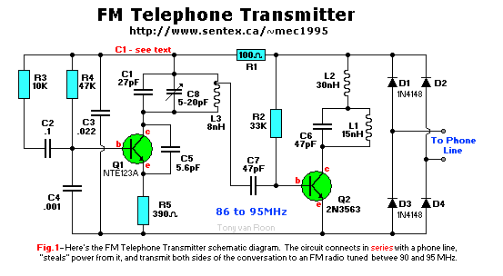
Schematic diagram

This circuit is connected in series with the End OR Ring (green or red) terminals of the telephone line. Power for the circuit is a full wave bridge rectified by diodes D1 through D4. The other 2 wires are black and yellow and are not used in most residential areas unless you have a second line somewhere.
Transistor Q1, capacitors C1 and C8, and inductor L3 form an FM oscillator operating at a frequency of approximately 93 MHz. Variable capacitor C8 allows the oscillator frequency to be tuned between 86 and 95 MHz. To move the tuning range to the 90 – 95 MHz range, C1 must be replaced with a 22pF capacitor. The tuning range can be extended even higher, to over 100 MHz, by replacing C1 with a 15pF or 10pF capacitor. Assuming the pick-up voltage is the standard 48V as in Canada and most US states. If the open voltage of an extension telephone network is lower, say around 39V, C1 needs to be 15pF to 10pF lower to be tuned for the commercial FM band.
The audio from the telephone line is connected through R3 and C2 to the base of Q1, where it modulates the frequency of the oscillator. Transistor Q1, inductor L1, and capacitor C6 form a power amplifier circuit. The signal leaving L3 in the oscillator circuit is fed to the base of transistor Q2, and the FM signal is passed through the collector of Q2. Inductor L2 is a radio frequency shunt that separates the power and audio from the amplifier circuit.
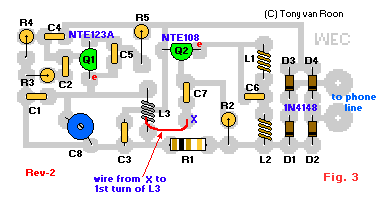
The coils L1 and L2 are six and eight turns of enameled copper wire, respectively. If you are winding your own coils, use approximately 22 gauge wire and a 1/8″ drill bit as your winding method. Any enamel on the ends where the coils will be soldered must be sanded, scraped, or burned off with a soldering iron before the solder will properly adhere to them. Coil L3 is six turns of tinned copper wire that should be spread out so that the coils have about 1 millimeter between each turn; none of the turns are allowed to touch each other or the printed circuit board itself! Once you have finished spreading the turns of this coil, the total width will be about 3/8″ (9mm). Again, this is approximate and depends on your skill. Don’t worry too much about it. You can always spread it out more or tighten it up a bit once the coil is assembled.
A tap is connected between the top of the first turn of L3


Be sure to check the board for errors before connecting it to the telephone line. The transmitter has a range of less than 100 feet. However, this distance can be increased by soldering a wire antenna (approximately 5 feet (150 cm) of 26 gauge wire) to the collector of Q2.
Connect the Transmitter to the telephone line using your preferred method. Make sure it is connected in SERIES. with only one (1) of the two wires! This means cutting either the RED (Ring) or GREEN (Tip) wire and hooking the loop between the single wire you just cut.
Turn on a nearby FM radio and tune to a quiet spot on the dial between 85 and 95 MHz (no stations are using this frequency). Pick up the phone; you should hear a dial tone on the FM radio right away. Otherwise, adjust the Clipping Capacitor C8 until you hear a dial tone. Adjust C8 first for best reception, then fine tune the radio.
If you have trouble finding a quiet enough spot on the dial, note that replacing C1 with a 10pF capacitor will change the tuning range to the 98-105 MHz range. Using a 22pF cap will set the range to 90 to 95MHz. These ranges also depend on the coil spacing.
The picture of C8 shows the blue color used for the prototype. The actual color of this trimmer capacitor changes as quickly as the weather (the current color is red). Since the printed circuit board is so small, components such as C8 and the three coils L1, L2 and L3 may need to be “bent” in place. (Don’t forget to scrape the coating off the leads before soldering!). All other components are best mounted ‘flat’.
Parts list:
Semiconductors:
Q1 = 2N3904, NTE123A, BC107, PN100, 2N4401, 2N2222, etc.
Q2 = 2N3563 or NTE108, *ONLY!*
D1-D4 = 1N4148, signal diode
Resistors, 1/4W, 5% tolerance:
R1 = 100 ohm (brown-black-brown)
R2 = 33K (orange-orange-orange)
R3 = 10K (brown-black-orange)
R4 = 47K (yellow-violet-orange)
R5 = 390 ohm (orange-white-brown)
Capacitors:
C1 = 27pF, ceramic
C2 = 0.1uF (100nF), ceramic
C3 = 0.022uF, (22nF) ceramic, 100V type
C4 = 0.001uF, (1nF) ceramic
C5 = 5.6pF, ceramic
C6,C7 = 47pF, ceramic
C8 = 5-20pF trimmer
Additional Parts & Materials:
L1 = 15nH (nanoHenry), 6 turns of #22 enameled copper wire (see text)
L2 = 30nH, 8 turns of #22 enameled copper wire (see text)
L3 = 8nH, 6 turns of #22 tinned copper wire (see text)
PCB = Printed Circuit Board
Optional: miniature alligator clips
Original Project © Mark Spiwak. Published in PopTronix Magazine by Gernsback Publishing in 1997. (Gernsback Publishing and POPTronix Magazine are no longer in business).
Disclaimer: Just for the sake of legal issues, here is our little disclaimer.
Depending on your country or state (province), most phone companies do not like anything connected to their phone lines. As such, by reading this disclaimer, you understand and agree to use this circuit at your own risk. The University of Guelph and/or Tony van Roon cannot and will not assume liability for the use or implementation of this circuit at any time and/or for any reason. This circuit may be used to share or record conversations, but is not intended for illegal activities. In order to use this device lawfully, you must be notified that the conversation is being recorded or monitored.
Telephone Transmitter FM Circuit Alternative link:
Şifre-Pass: 320volt.com
Publication date: 2010/08/03 Tags: analog circuits projects
Stereo 64LEDs VU Meter Circuit Atmega8
Generally VU Meter for the indicators used integrated 2 × 15 LEDs or 10 LEDs supports this circuit atmel microcontroller using more LEDs used VU-meter circuit ATmega8 microcontroller based on the two-channel stereo per channel 32 LEDs are dropping a total of 64 LEDs PCB drawings hex and c code There.