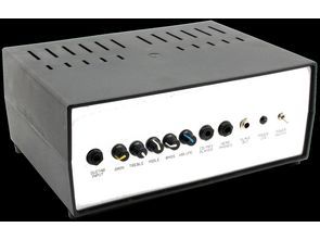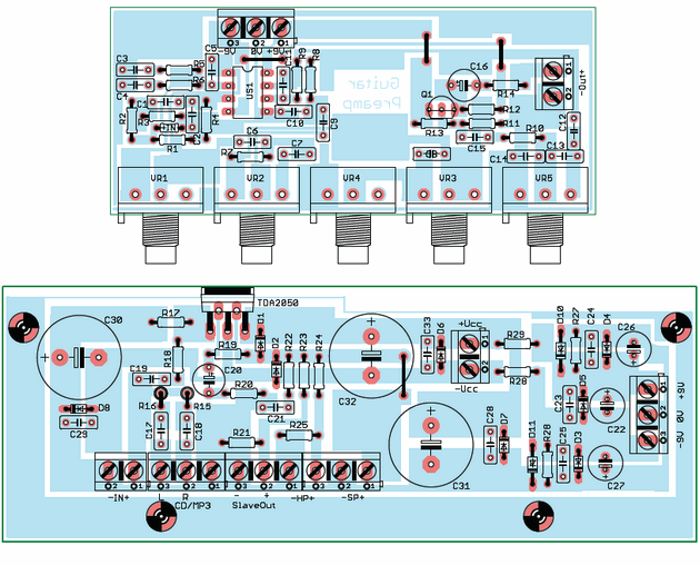
Guitar Amplifier circuit the signal is directed to the tip of the TDA2050. The output power is 25 W with a load of 4 ? (17 W at 8 ?). This block is equipped with an additional “CD / MP3 Player” input and three “Slave Out” outputs (for other terminals or recording equipment), “Headphones” (for headphones) and “Speaker Out” ). Power diodes are connected to the power output terminal in the locking direction relative to the power poles. This is to reduce the phenomenon of the stop when switching on and off the power.
Guitar Amplifier Circuit schematic diagram
The schematic diagram of the Guitar amplifier The amplifier can be divided into three functional blocks:
Preamplifier (input stage, color correction, amplification, voltage follower).
Power Amplifier (Power Amplifier for Speaker or Speaker Unit).
Power supply unit (unit responsible for powering the entire unit).
The input stage was made on one of the two operational amplifiers housed in the NE5532 integrated circuit enclosure. These include: resistors R1 … R6, capacitors C1 … C6 and potentiometer VR1, which is used to pre-adjust the gain. Input impedance defines resistor R1 and it is 1 Mohm.
The sensitivity of the input is about 0.5V and is optimal for the electric guitar. This allows the preamplifier to adjust the input stage without problem. The voltage gain of this stage is in the range of 29dB for the bass and 35 dB for the high tone.
Strengthening the extreme bands fills the frequency response gap of the electric guitar transducer. As a rule, single coil electric guitar transducers range from 150 … 300Hz to a maximum of 6 … 10kHz, as a result of transducer construction. The average impedance of this transmitter is about 4 kV, although it is safe to assume that it is within the range of 2 … 6k.

The “single coil” is “brighter” in tone, has a lot of “center” and less bass. The case is slightly different with dual humbuckers. This transducer works in the range of 100 … 200 Hz to 5 … 8 kHz.
Guitar Amplifier sample
The guitar loudspeaker works in the range of about 100Hz to 5kHz, but the frequency response in this band is nonlinear and one could risk the assertion that as many guitar models are, there are so many different characteristics of these speakers. That’s why the preamplifier was designed to “squeeze” as much of the guitar sound as possible and put that sound into a guitar speaker.
FILE DOWNLOAD LINK LIST (in TXT format): LINKS-25834.zip
Publication date: 2017/10/01 Tags: audio amplifier circuits, ic amplifier

E-Gitarrenverstärker + Vorverstärker
Guitar Amplifier Schaltung Das Signal wird an die Spitze des TDA2050 geleitet. Die Ausgangsleistung beträgt 25 W bei einer Last von 4? (17 W bei 8?). Dieser Block verfügt über einen zusätzlichen “CD / MP3-Player” -Eingang und drei “Slave Out” -Ausgänge (für andere Endgeräte oder Aufnahmegeräte), “Kopfhörer” (für Kopfhörer) und “Lautsprecherausgang”. Leistungsdioden sind mit dem Leistungsausgangsanschluss in der Verriegelungsrichtung relativ zu den Strommasten verbunden. Dies dient dazu, das Phänomen des Stopps beim Ein- und Ausschalten der Stromversorgung zu reduzieren.
Schematische Schaltung des Gitarrenverstärker-Stromkreises