I don’t use a soldering iron too expensive for everyday use. 30W is sufficient for mounting those, but it’s hard to solder thick wires and chassis. In these cases, 40W soldering iron is inevitable, it makes for cheap of this stuff deteriorates in a very short time.
40W soldering iron and a middling one of the best dimmer I adjust the voltage, open circuit when mounting the chassis, unsolder until the end when 25-30W I’ll turn down the resistance between, it’ll be also more long-lasting dimmer circuit I started looking for.
the
dimmer circuit diagram
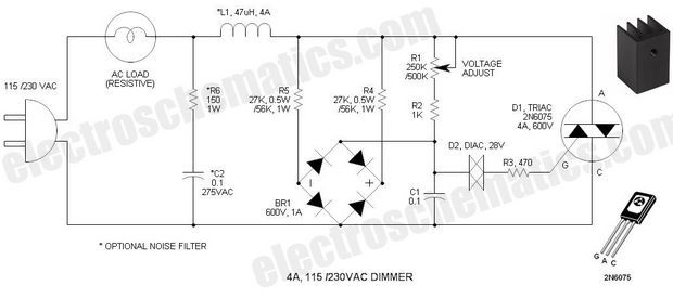
source: http://www.electroschematics.com/10115/triac-lamp-dimmer-snap-on/
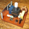
Schema, but didn’t plan on a nice sit down and not necessarily have drawn any mounting soldering. 5×5 cm was able to fit a card. I’ve done it before crackling and noise in a dimmer circuit is quite simple in this circuit, I was irritated by the event I have met with such an incident. After the addition of noise at the output of the circuit of the four diodes in the rectifier circuit or network n’t laid, I don’t know, but it more than met my expectations.
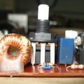
I used my hand as a bt138 triac for. Counterpart many will fit without trouble. 40W soldering iron doesn’t heat up almost no triac load is coming probably less, but still a small plate cut out of aluminum and the screw was
In the circuit the coil 47uh filter is listed, but didn’t give any trouble 120uH in my hand. Delight put in a small plastic box under the table and was bolted to a side. The output type of one is also the plaster I gave it to the outlet. Thus, voltage-regulated outlet. But only pencil soldering to connect.
This outlet connects to another device and accidentally cut the voltage If your device can become corrupted. Near the outlet, or paste it into you post a warning or to block someone else from a way to use this outlet.
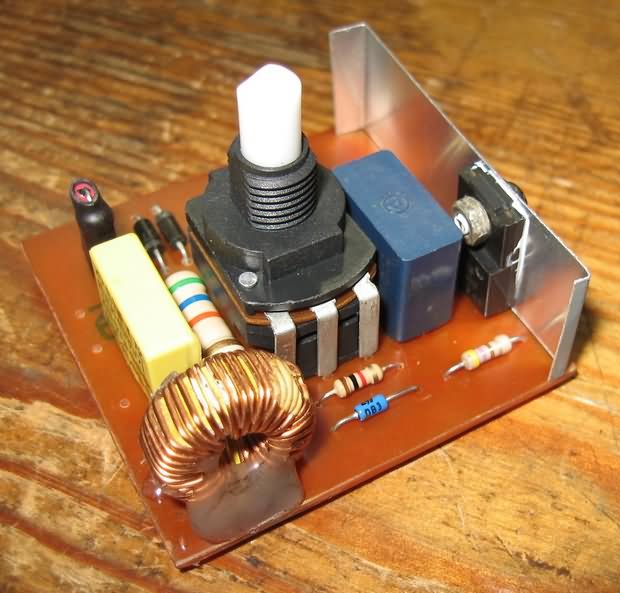
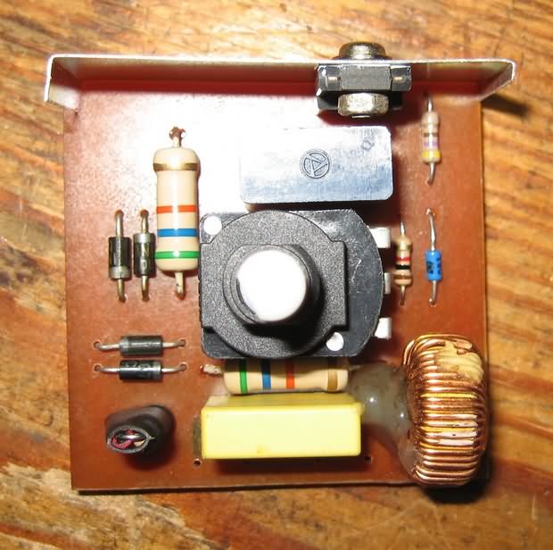
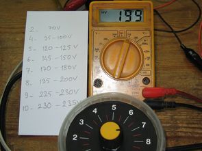
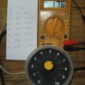
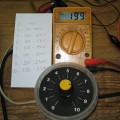
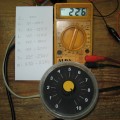
I wrote the paper in the Inbox with the picture may be slightly different voltage values in the network because avometers don’t stay in place much tension. Measure the paper after writing the first time and the second time when taking a picture, volts 235 volts mains voltage in the vicinity of 226 landed. The key when first turned on, the 65-starting around 40V, the potentiometer 1.2.3. it doesn’t create too much voltage difference in the ranks. Potentiometer dimmer potentiometer in the picture so be careful if you switched the type of plastic on each side sold as.
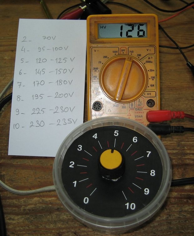
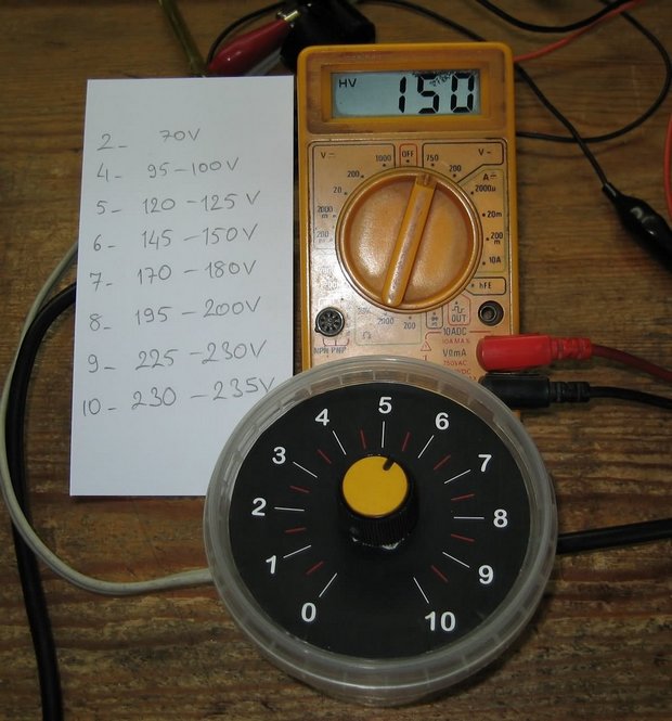
Belonging to the dimmer circuit pcb, schematics, drawings dial:
FILE DOWNLOAD LINK LIST (in TXT format): LINKS-25416.zip
Published: 2016/04/22 Tags: power electronic projects
TEA2025B stereo Amplifier circuits
the TEA2025B battery 6V stereo Amplifier circuits that will work with my goal of making an amp that could power enough and relatively practical.
In fact, this recipe is more Class D amfile and ready to comply with but is not because I don’t want to use the chance to get this out of my hands I headed Tea2025B eat.
TEA2025B circuit diagram
Dimmer-Stromkreis 40W für Lötkolben
Ich glaube nicht, verwenden Sie einen Lötkolben zu teuer für den täglichen Gebrauch. 30W ist ausreichend für die Montage, aber es ist schwer zu Löten, dicken Drähten und Gehäuse. In diesen Fällen, 40W Lötkolben unvermeidlich ist, macht es für Billig, das Zeug, verschlechtert sich in sehr kurzer Zeit.
40W Lötkolben und einer mittelmäßig, einer der besten dimmer I einstellen der Spannung, offener Stromkreis, die beim Einbau der chassis ablöten, bis am Ende bei 25-30W werde ich drehen Sie den Widerstand zwischen werde es auch langlebiger dimmer-Schaltung, die ich suchte.