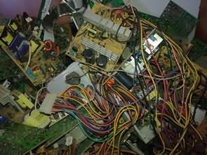
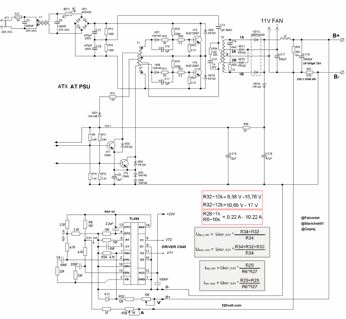
A modification to convert an old generation ATX or older AT computer power supply to a 4AH..100AH battery charger. You can add a TL494 controlled module to the power supply and make a high power charger that works very well after a few tweaks. The output voltage of the circuit can be adjusted between 10.6v….17v and the current is 0.22ma…. Between 10.22A. For transformer compatibility, you need to use a power supply with TL494 on it, but it can be used on cards with AT2003, AT2005, SG6105 integrated, as far as I remember, the transformers are the same..
There are A,C,D and E versions of the modified, I made the E version which is stable lastly. In this arrangement, current sensing is at the output, there is no current fluctuation synchronized with the inductor, and therefore the operation of the error amplifier detects the fluctuations better.
AT, ATX Power Supply Charger Circuit Diagram
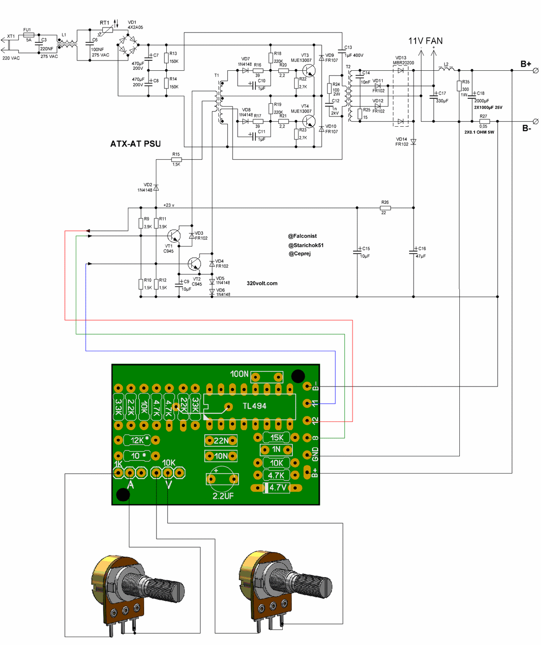
As you can see in the video, it is easier to apply as an additional module and the cost is less. The module PCB I prepared is very small, measuring 4.5cm.3.1cm. You can add a relay or mosfet against the reverse connection of the battery.
Battery Reverse Connection Protection Circuits
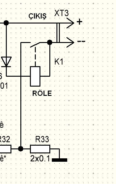
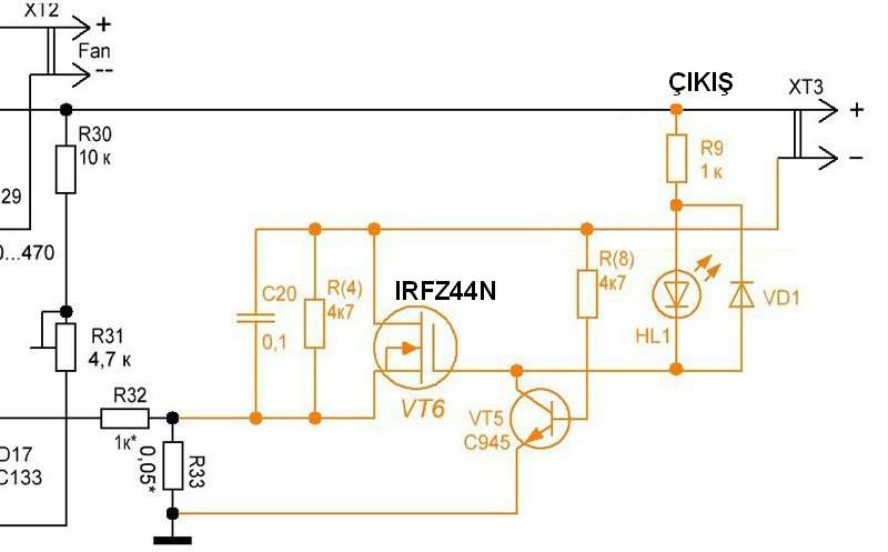
Caution: Do not use this circuit as a regulated power supply designed for battery charging.
PCB drawings designed for charging module and Cdrom box, at, atx power supply box: 28791a.rar pass: 320volt.com
Source radiokot.ru/forum/viewtopic.php?f=11&t=39128
Publication date: 2023/04/07 Tags: battery charger circuit, power electronic projects, smps circuits