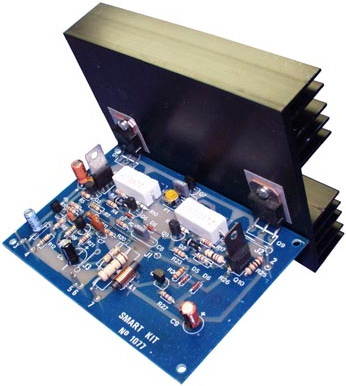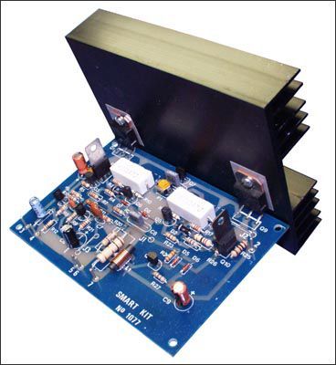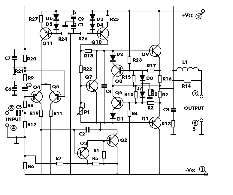
A quality amplifier circuit with low distortion, high sensitivity, output short circuit protection, delivering 100W of power.
Amplifier Circuit works with a symmetrical +-40 VDC power supply and draws a maximum current of 2.6 A. If it is to be used with 8-Ohm loudspeaker, 2 amp fuse should be connected to the supply line. If 4-Ohm loudspeaker is used, 3 or 3.15 amp fuse will be used.
100W Amplifier Technical Specifications
Output power (f = 1 KHz, d = 0.5%): 100 W at 8 ohms
Supply voltage: ……………. +-40 VDC
Quiet current: …………. 50mA
Maximum current: ………………… 2.6 A
Sensitivity: . 600mV
Frequency response: ………… 10-35000 Hz (-1 dB)
Distortion THD: …………….. 0.01%
Intermodulation Distortion.: ………0.02%
100W Amplifier Attenuation Current setting
Connect an ammeter to the + section in the supply circuit. Adjust the P1 Trimpot until the current drawn when the Amplifier Circuit is idle (without connecting the speaker) is 50mA, although it does not hold the full value, it should be a close value
supply voltage of the circuit is 2x40v dc total 80v dc be careful. The lull setting is done with P1 1k trimpot. It will be set as 50mA.


100W Darlington Transistor Amplifier Circuit PCB schematic alternative link:
Şifre-Pass: 320volt.com
Published: 2008/04/01 Tags: audio amplifier circuits, transistor amplifier
PICmicro PC Keyboard Interfaces PIC16C74 PIC16F84 PIC16F77
PC Keyboard Interface LCD display with LED projects have different applications in the most excellent source of resources to be asm code 🙂 protocols and a lot more information about the scheme’s details