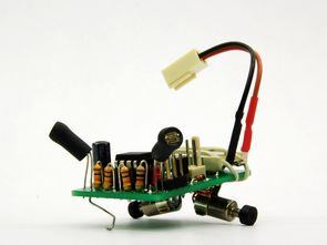
Light following robot circuit board on attiny25v not very complicated circuit Lithium-polymer battery provided with the circuit feeding the tiny H-bridge output (2N3904) drive motors are controlled with two LDR light is perceived. As you can see in the pictures material placement and cute 🙂 quite well also in the video seemed to be running very stable robot.
Light Following Robot Project
The materials used in the robot at half;
Attiny25v (microcontroller)
MPC1700 (3.3v regulator)
2X LDR
2X 10 kOhm resistor
2X 470 ohm resistor
2X 2N3904 transistor
2X 1N4148 diode
100nF capacitor
100uF capacitor
Lithium-polymer battery 3.7 V 100 mA
2X Fuse holder
Pager motor 2X
Heat-shrinkable sleeving
rubber tubing
6-pin ISP connector
Atmel attiny25v following robot project with the source of light c eagle pcb software and shared schema files Source: http://tinkerlog.com/2009/07/24/tiny-braitenberg-vehicle/
Şifre-Pass: 320volt.com
Published: 2010/04/21 Tags: avr project, microcontroller projects


Atmel Atmega8 via USB Control Circuit
Hi, I have done recently attiny2313’l usb application (ATTINY2313 PIC16F88 USB UART converter circuit) then one needs at this time on I did with ATmega8. RS232 portion of the circuit 15 disuse I / O pin with a control board that communicates via usb I designed.
Available in 15 out of 15 relay circuit on a plaque by Cover with too much space. Relay outputs to observe instead I added diodes. We also work with 1,2,3 led to the exit to observe’ve added 3 relays. Circuit fine çalışıyor.atmega8 ‘s usb output due to the hassle of opening and closing process is a bit slow, but speed is sufficient for the control board.