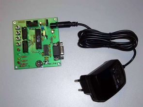
Atmega8 Microcontroller with PLC function is a computer-connected control card, of course, does not have very advanced features, but a successful application that will inspire has been shared in the above sources
Some features of the PLC Card;
Digital inputs TTL or 5V CMOS 4 pieces
Digital outputs TTL or 5V CMOS 4 pieces
Analog input 5v 2 pieces
PWM output 4 pieces
RS232 Communication (Baud rate bps 57600 57600)
Flow control

A nice detailed study Atmega8 fuse settings, connection expansions and many more details are given.
The programmable Basic controller is a simple device that can work as a PLC (program logic controller) for home automation, control, etc. The controlled system can control some processes, temperature regulation, battery charging, education and hobby purposes.
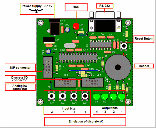
It has analog and discrete input/output and an RS232 interface for communicating with other devices and restarting a control program. The control program is a text version of the BASIC language. The main task of the controller is to interpret BASIC commands. The TBC version of the BASIC language has commands for working with discrete I/O, ADC and PWM. The appearance of the controller PCB is shown in Figure 1 below.
The frequency of the 10-bit PWM is 5.4 kHz.
The 10-bit ADC Conversion time is approximately 30 usec, but the actual sampling depends on the program cycle.
The current through the discrete outputs should be limited to 20 mA.
Note that one LED is connected to each of the discrete outputs. The current is approximately 8 mA per LED.
Source: http://www.cqham.ru Atmega8 plc circuit alternative link:
Şifre-Pass: 320volt.com
Publication date: 2010/05/18 Tags: atmega8 projects, avr project, microcontroller projects
FT245BL USB Logic Analyzer Circuit 8-Channel
PIC18F4580 made with 4-channel logic analyzer circuit I shared 8-channel logic analyzer circuits having the microcontroller use made of the USB logic analyzer circuit usb interface for the FT245BL used other help integrate the LM339 op amp and CD4069, CD4093 an additional power source without the need for direct USB port is supplied through all the driver files , with borland Delphi7 source code analyzer program and the eagle are drawings PBC scheme.