On the Internet, atmel, microchip series microcontrollers with a lot Led cube has a project in this application one of them, but diagrams, photos, supplemented with a detailed description there thanks to this project Led cube understand the logic may be easier to floors circuit diagram and C source software provided.
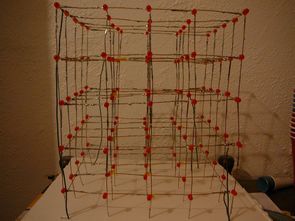
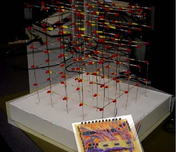
5x5x5 LED cube dimensions 512 x red leds placement of the LEDs will be a bit erratic but it has involved a lot of precise soldering LEDs 🙂
Led cube of the main materials used in the circuit outside ATmega32 CD74HCT238 decoder and 74LS04 Hex Inverter


Our project is an orientation independent 3D LED display in one sentence. We were inspired by various videos of similar cubes on youtube and also the idea of creating an interactive 3D display.
We created a 5x5x5 LED cube display and controller board that connects the cube to a Mega32 microcontroller. We can display a wide range of low resolution 3D images or animations on our cube and we use an accelerometer to detect the horizontal or vertical orientation of the cube and adjust the display so that it remains upright even if we turn the cube sideways. The cube was used to display a message (“ECE476 FINAL PROJECT DEMO”) and a small light show animation.
We got the inspiration for our design when we saw one of the many videos on youtube about 3D LED cubes. Given the budget and time constraints, we thought the idea of a 3D display was interesting but challenging and we also thought we could take the idea a step further (this extra step was to adjust the orientation using an accelerometer).
One of the main considerations when first designing our cube was deciding how big to make it. Obviously, more LEDs would provide better resolution and allow us to display some more interesting images, but we were also limited by how big a cube we could produce in a given amount of time, and even more so by how many LEDs we could reasonably control given the limited number of port pins and the limited processing power of the Mega32. We eventually settled on a 5x5x5 cube as a reasonable trade-off between size and practicality, but given similar time and budget constraints, we encourage future groups and others interested to build a larger cube (we recommend 8x8x8, because that gives you a nice round 512 LEDs).
The next important consideration was how to control all the LEDs. A 5x5x5 cube made for 125 LEDs, which is many more LEDs than there are ports on the Mega32. Initially, we developed a method for controlling each LED individually, very similar to the method used in common LED drivers. The method involved sending a serial bit stream representing the state of each LED to a 125-bit serial input parallel output shift register.
After changing the state of each of the 125 LEDs, we would latch the value of each bit using 125 flip flops and turn each LED off from one flip flop output. This method required only 3 connection pins (one for the serial bit stream, one to clock the shift register, and one to clock the flip-flops) and was very fast, because we could run the shift register at over 1 MHz and theoretically update all of the LEDs in a few hundred microseconds. In theory, this method seemed very fast, but in practice it was extremely inefficient.
The main problem with controlling each LED individually was that we had to run at least 1 wire to each LED to do this. This problem quickly got out of hand; at least 6 wires would have to come out of each of the 25 columns at the bottom of the cube. All of these wires would make for an aesthetically unappealing cube, and we would have to ask how we were going to get all of these wires together and fit them into the base of the cube. We realized that we needed to connect the LEDs in a way that we could address them individually without having to run a separate wire to each one. This was a difficult problem, because a typical addressing scheme of selecting a column, then a row, then a level would have the undesirable side effect of lighting up more LEDs than we wanted.
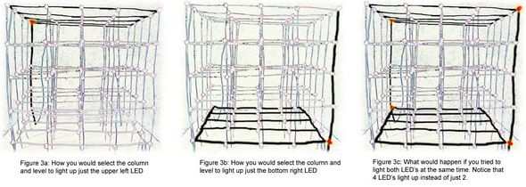
After some thinking and searching, we finally found this website that gave us a great way to do it. The tutorial showed us that we could address the LEDs one by one without having to run a ton of wires. To do this, we connect all of the top and bottom columns of LEDs to the same positive terminal (25 columns total, 5 LEDs each), and then all of the horizontal levels to the same ‘ground’ (5 levels with 25 LEDs each). To select a single LED, we apply 5V to the column where the LED is located, and then ground the level it is on.
This way we were able to select each LED individually using only 25 control lines for the columns and 5 control lines for the grounds. However, if we tried to light more than 1 LED at a time, this would still result in the problem of the previous external LEDs being struck by lightning. As shown in Figure 3, if we wanted to light only the first LED on the top level (back left corner) and the last LED on the bottom level (front right corner), we would set columns 1 and 25 to high and then ground the top and bottom levels. However, if we did this, instead of only lighting 2 LEDs, we would have 4 LEDs (top and bottom of the back corner and top and bottom of the front corner). To get around this, we try to light only the LEDs in one column at a time. To display images with LEDs lit from multiple columns, we would switch
Source: people.ece.cornell.edu alternative link:
Şifre-Pass: 320volt.com
Publication date: 2011/08/07 Tags: avr project, led projects, microcontroller projects
HDD Brushless Motor driver Circuit Atmega8
Brushless motor drive circuit used in computers hard drive with Atmega8 checked the engine ATmega 8 output MOSFET (IR4427, IRFZ44) strengthened engine with A, B, C, D, attached to either end. Software is written in C language compiler used in CV AVR application circuits for frequency crystal oscillator is used but instead of the internal crystal oscillator recommend testing for long-term operation of the motor is estimated that 30,000 of cycles.