Animator is actually a 5×16 LED matrix device used to display simple animations :). Initially, the device was used for something completely different and was controlled directly from the parallel port using a program written in Pascal. The idea turned out to be a bit wrong, as the program does not provide an even refresh rate. The layout was in a drawer for a while, until a vacation day, I was suffering from having too much free time 🙂
I remembered this project and thought it could be used somehow. But the LPT port was already filled with a 2×16 LCD screen, so I created an adapter for the serial port (using AT90S2313 top processor) and wrote the appropriate software.


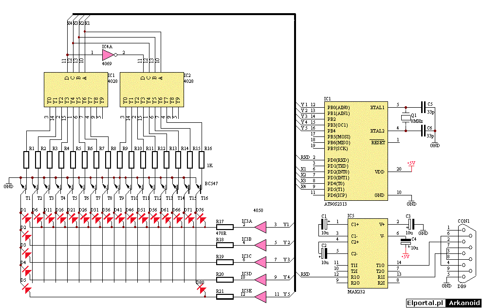
The schematic representation of the system is below. D1-D80 diodes consist of 5×16 led matrices. I was surprised to myself that I once wanted to solder it to a universal board… 🙂 IC1, IC2, IC4 circuits form a 1/16 decoder that controls the display columns through T1-T6 transistors. The anodes of the diodes are turned on through the non-inverting buffers of the IC3 circuit. Resistors R17-R21 limit the LED current. The IC5 functions here as a typical serial port interface. The last and most important element is the AT90S2313 superprocessor, which receives data from the serial port and controls the diode multiplex matrix. The system is fed with +5V from the computer’s power supply.
The program located in the upper processor is not very complex 😉 The Windows application reads the individual animation frames from the text file and sends them to the screen, so that the animations are not stored in its memory. The main loop of the program is to receive. consecutive bytes from the serial port and save them in a sixteen-element array. The variables make up the individual frames, which in turn make up the entire animation.
An interruption from Timer0 (listed below) causes the variable “Pos” to increase, thereby controlling the next column of the display and transferring the next variable from the table to portB (diode anode). The screen is refreshed at a frequency of 50Hz.
I did not design a PCB for this chip as it is still a prototype. I usually mount test versions of circuits on universal boards – mistakes are often made when designing a circuit and it’s much easier to make any changes to the “universal”. The “Light board” project was published in EdW 8/2002. The documentation of this project (in pdf format) is available on the Elportal server at: Programmed light board (388KB)
Why am I writing about this? This system uses two ready-made 5×8 LED matrices, 89C2051 processor, is programmed from the serial port and can be easily adapted to the needs of the animator. If someone has this system, they can convert it with very little effort. The 2051 microprocessor can be replaced, for example, with the ATmega2313 – then there is no need to change my software.
Enclosure fabrication and assembly
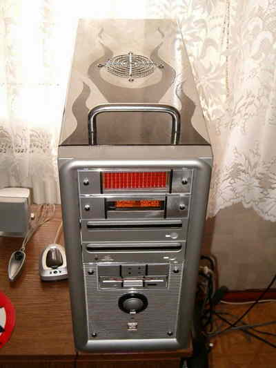
The first version of the Animator was housed in a simple silver-painted plastic enclosure. The device was illuminated from the bottom by two super bright blue diodes and everything was in the computer case. It looked rather strange, but at the same time unusual. There was one small problem though. To remove the side panels on my computer, I first have to remove the top of the case. So whenever I wanted to get inside the computer I had to remove the screen which was a bit inconvenient. So I decided to open a whole new case…
… that can be plugged into a 5.25-bay computer (such as a CD-ROM drive). I decided to make the new nest out of wood, as it is easy to work with.
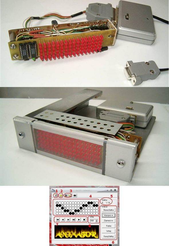
The front is the original plastic plug from the computer. I drilled a hole for LED matrices with dimensions of 28x86mm. At the bottom of the structure is 5mm plywood measuring 14x18cm. After cutting the side and top laths (25mm wide plywood), I bent the entire structure with modeling clamps, previously greased all joints with Distal two-component adhesive. The next day, after the glue had dried, the casing turned out to be strong enough and I could move on to the next step, painting.
I didn’t have much choice in terms of color. The entire computer is silver, so the animator’s case must also be silver… I applied several coats of spray paint. I did not use a primer. I also didn’t smooth the surface of the wood because I found the safe mostly hidden and unnecessary on the computer.
I screwed the screen and adapter to the wooden base and glued the molex plug to the top strip. By reading my articles, you can conclude that he treats everything with glue. Not everything, but certainly many things :). We are currently able to purchase a wide variety of adhesives for very different applications. Use it to make your life easier :).
PC Panel LED Animator work
Source edw.com.pl PC Controlled AT90S2313 Led Animation Circuit source code schematic pcb files alternative link:
Şifre-Pass: 320volt.com
Published: 2008/10/23 Tags: avr project, microcontroller projects
ATmega16 AVR Test Board for Beginners
Atmel ATMega16 that you develop with projects to try to develop a multifunction test, development board LCD connector UART input LEDs display various adjustments for the dip switch and control buttons have an external 12 volt supply is working with also protel and sprint layout prepared by the source PCB files available
ATmega16 AVR experiment board