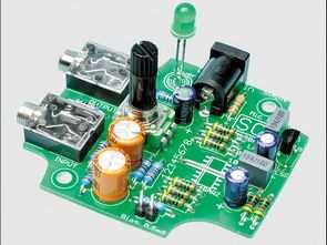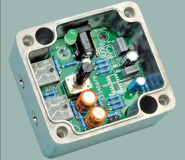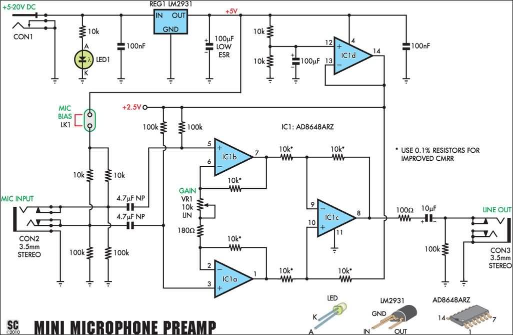
The microphone preamplifier circuit operates with a dc voltage between 5 volts and 20 volts. The measurement and operating characteristics are quite good. The printed circuit design based on the AD8648ARZ SMD Op amp is very good. As in practice, if an aluminum box and 9v alkaline are used for power supply, it gives very good results.
Microphone Preamplifier Circuit

High Performance Microphone Preamplifier
Some recording devices, especially computer sound cards, have poor sound quality or insufficient gain when used with certain microphones. This small module provides line level output from an unbalanced or balanced microphone and has very low noise and distortion. It operates on 5-20V DC, drawing only 6mA.
Unbalanced or balanced mono input (3.5mm mono/stereo socket)
Unbalanced mono output (3.5mm mono socket)
Very low distortion and noise
5-20V DC plug pack or battery operated
Wide adjustable gain
Line level output to at least 1.5V RMS
Electret microphone bias (approx. 390µA)
Supply voltage: 5-20V DC (operates at 2.8-5V with reduced performance)
Supply current: typically less than 6mA
Voltage gain: 3-111
Input sensitivity (line level output): 14mV RMS
Input sensitivity (1V RMS output): 18mV RMS
Input impedance: 50kΩ (8.3kΩ with bias enabled)
THD+N ratio: 0.0035%
THD+N ratio (10mV RMS input): 0.014%
Signal-to-noise ratio: -90dB (-93dB A-weighted)
CMRR* (1% resistors): -55dB
CMRR* (0.1% resistors): -88dB
Frequency response: 20Hz-20kHz ±0.01dB
Signal processing: >1.5V RMS output
Signal processing (3.0V supply): >1.0V RMS output
Note 1: CMRR = Common Mode Rejection Ratio Note 2: All specifications are for 50mV RMS input, 775mV RMS output, 20Hz-22kHz bandwidth and 6V supply unless otherwise stated.
The reason a microphone preamplifier is needed is that most microphones, especially non-powered types, have a low output signal level. A typical microphone will output 10-200mV RMS at maximum volume. Audio “line level” is around 775mV RMS (0dBu) or higher, but many audio equipment can actually handle 1V RMS or more. Higher signal levels usually mean more dynamic range.
Therefore, to connect a microphone to a mixer, computer sound card, amplifier, etc., we need to insert a preamplifier in between to boost the signal level. Otherwise, it may not be possible to get enough volume.
Some of these devices include built-in amplifiers, but they do not always perform well. Built-in microphone preamplifiers can be noisy and may not provide enough gain for some microphones (i.e. those with very low output levels). Many, if not most, computer sound cards do not use high-quality analog components.
Adding a microphone preamplifier does not guarantee good results, as the line-level circuitry can still introduce noise and distortion, but it certainly increases your chances of getting acceptable sound quality. On the other hand, a preamplifier is a must for connecting a microphone to any equipment that only has line-level inputs.

This preamplifier has very good performance despite its low power requirements. Signals below 50mV RMS will cause worse performance, while higher level signals will provide better performance. For a 25mV RMS input, the signal-to-noise ratio will be reduced by 6dB, for 12.5mV by 12dB, and so on. With a 100mV RMS input, the S/N ratio increases to 94dB and THD+N increases to less than 0.002%.
Performance does not vary with signal frequency. The frequency response is very flat with -3dB points at about 1Hz and 1MHz (see Figure 1). The total harmonic distortion plus noise (THD+N) level is uniform throughout the audible band (see Figure 2) and consists mostly of noise at typical microphone levels.
Under our test conditions of 50mV RMS input and 775mV RMS output, harmonic distortion only makes up 12% of the total distortion measurement, primarily the second harmonic.
Such a wide frequency response is not necessary, but it is a result of making this project as small and simple as possible. There is no low pass filter other than the internal compensation of the operational amplifiers. We assume that most devices that accept line level signals will have their own band pass filters to remove frequencies outside the audio spectrum.
Common Mode Rejection Ratio (CMRR) is a measure of how well a device with a balanced or differential input can reject a signal common to both inputs. In other words, if the same amount of 50/100Hz hum
Source: http://www.siliconchip.com.au/cms/A_112108/article.html Microphone Preamplifier Circuit pcb, schematic alternative link:
Şifre-Pass: 320volt.com
Published: 2010/11/23 Tags: audio control circuits
GPS Circuit Boats Computer PIC18F4550 Microcontroller
Generally known as PC Tools has prepared a project 🙂 but siliconship in the boat’s GPS system tracks the GPS module EM 408 and mikrodenetleric pic18f4550 usb connection to the circuit there also. 2X16 LCD Indicative date, etc. on the location of the clock compass. Viewing a lot of information. GPS circuit does not include the source code of the software given hex code but with PIC18F4550 circuit design, details can inspire people interested in programming this reason, I wanted to share
GPS Circiut Boats Computer