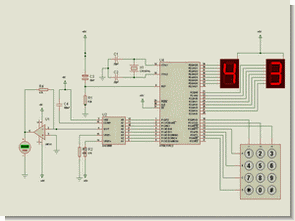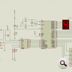
Circuit Operation: Circuit diagram appears in the 0-5 the entered value from the keypad circuit, which is connected to port P1 applied to the integrated DAC 0808 DAC output is obtained from the analog voltage.
P0 port is connected to the 7-segment display of the absolute value of the voltage, which is connected to port P2 indicator shows the decimal value of the voltage. On the keypad “*” key to delete the entered value, “#” key, the entered value is used to convert the analog voltage.
Output of 0-5 V 0.1 V-0, 2Volt precision analog voltage is obtained.
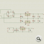
Programmable Power Supply Circuit Diagram
8051 Programmable Power Supply Keil source code proteus pcb simulation files: AUTHOR: @Ali İhsan UYSAL
Şifre-Pass: 320volt.com
Published: 2008/12/22 Tags: 8051 example, avr project, keil example, microcontroller projects


555 Example Circuits
555 demonstrate the use of integrated square wave oscillator circuit on a simple counter and Proteus simulation drawings.
0-99 counter circuit (you can set the count rate with variable resistor RV1)
10 Led king circuit rider (you can set the speed of light LEDs with a resistor RV2)
29 Led Animation circuit (resistors RV1 with the LEDs, you can set the speed of light)