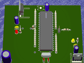
Prepared for the 8051 series microcontrollers experiment cards and additional modules. All cards eagle drawings have been prepared by the printed circuit board and scheme. Other modules arranged pic except for the main card, av series can be made to work with microcontrollers.
Additional cards: Thermometer (SMT160-30 SMT160-30) RS232, LCD I2C EEPROM, external memory (62256), DAC expansion module (8255), Button module with 8 × 8 LED matrix, led module, AT89C2051 module
Additional boards: Thermometer (SMT160-30 SMT160-30) RS232, LCD I2C Eeprom, External memory (62256), DAC Expansion module (8255), Button module, 8×8 LED matrix, led module, AT89C2051 module
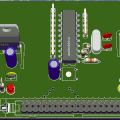
8051 motherboard
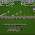
A board with a “big” processor. It only contains the processor, 5V power supply and 12V power supply, a system connector for connecting expansion modules.
Thermometer
Board with IO SMT160-30. SMT160-30 is a temperature=>current converter. Both cases (TO220 and TO92) can be installed on the board, but only one of them can be installed.
RS232 interface
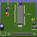
This board is connected to a large connector. It has two of these connectors, we can connect other modules to the other. The motherboard is designed to be used when communicating with a PC via a serial port.
LCD Board
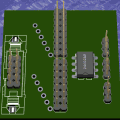
An LCD display can be connected to this board. It contains both types of connectors (single row and double row). Trimmer R1 (left) adjusts the contrast of the LCD, while trimmer R2 (right) adjusts the backlight intensity on the LCD. The LCD is connected to two ports. One is 8-bit data, the other is control.
I2C EEPROM Board
The board contains a 24Cxx type memory, which is programmed and read via the I2C bus. It is possible to use several of these memories simultaneously on one port, because each memory has a different address, which can be set by jumpers A0, A1, A2. It is also possible to set which pin the clock pulse (jumper SCL) and the data pin (jumper SDA) will be on.
External memory Board
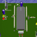
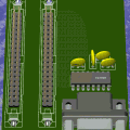
The motherboard is equipped with a 62xxx type memory, in my case 62256, a 32KB memory organized by 8 bits. The maximum addressable value of the 8051 is 64KB. If we need to use a different memory size, we can replace the IO with another IO with the same connected pins. This memory is wired to be used as program memory. The board is also equipped with two large connectors to connect other modules such as distribution boards. However, we should not forget that the RAM itself eliminates the P0 and P2 ports, which can no longer be used for anything else.
DA converter board
The board is equipped with resistors. The output of this board is an analog signal in the range of 0-5V. The board also includes an external input for displacement 0.
Port expansion board
The board is equipped with an 8255 circuit. This is used to create 3 eight-bit ports from one. However, it takes a few more bits from another port that it needs to control the communication.
8-button board
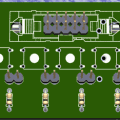
The board is equipped with 8 buttons to test the inputs. For each button, it is possible to choose whether it sends log.1 (jumper open) or log.0 (jumper connected) when pressed
8×8 LED matrix board
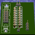
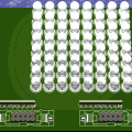
The board is equipped with 64 LEDs. It is connected to 2 ports. It serves to master the matrix display technique. When installing the LEDs, be careful to rotate all the LEDs in the same way.
8 LED board
The board is equipped with 8 LEDs to test the logic outputs. I recommend installing sockets instead of LEDs and then placing an LED on them, because it is possible to change the logic with a jumper. And this requires rotating the LED.
Distribution board
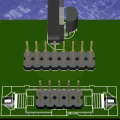
A board that separates the system connector into separate ports and power connectors
Şifre-Pass: 320volt.com
Publication date: 2011/01/29 Tags: development board projects
CNC Project ATMega16 X-Y-Z Motor Control Circuit
ATMega16 microcontroller based on a detailed cnc project with computer com RS232 on port communicating project’s source C code, schematics eagle CAM (graphic printout is used to direct the CNC circuitry and sent to) files bulunuyorayrı mechanic parts of 3-d images were shared. Test video with a simple picture drawn on the CNC. Motor Control Circuit