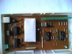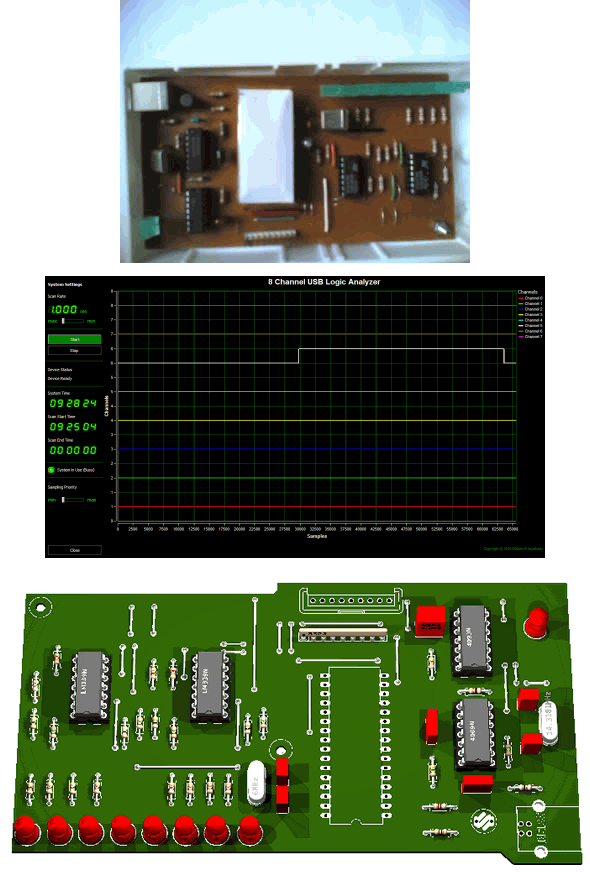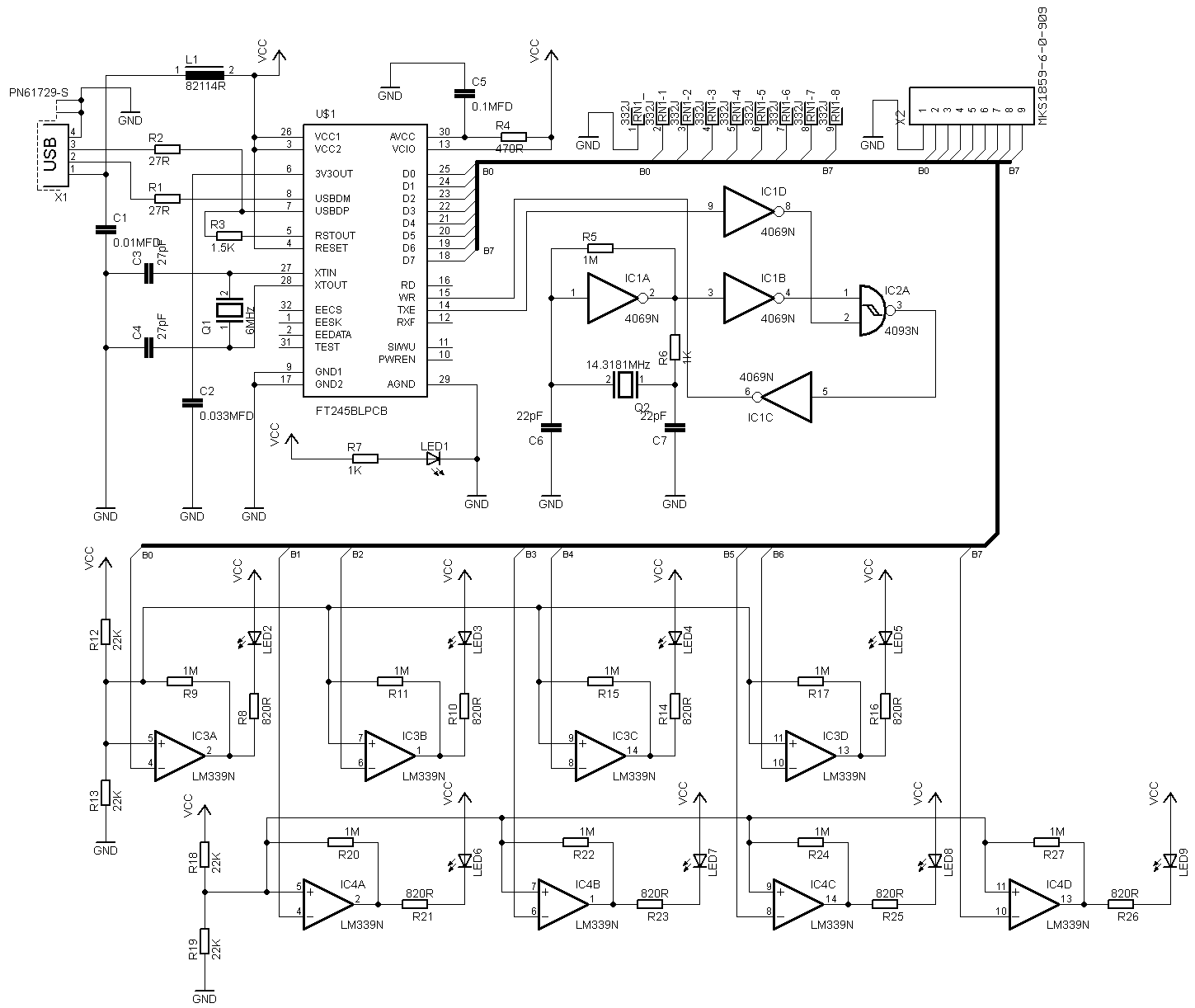
I have previously shared a 4 channel logic analyzer circuit made with PIC18F4580. The 8 channel circuit is made without using a microcontroller. In the USB Logic Analyzer circuit, FT245BL is used for the USB interface. Other auxiliary integrated circuits LM339 op amp and CD4069, CD4093 are fed directly via the USB port without the need for an additional power supply. All driver files, Borland Delphi7 source codes, analyzer program and Eagle schema pbc drawings are available.

Logic analyzers allow us to monitor and/or diagnose multiple digital signals simultaneously, and these devices are very important when developing complex digital systems. In this project, we designed a simple 8 channel USB logic analyzer with the Windows version of the driver software.
The design of this logic analyzer is based on the Future Technology Devices FT245 USB FIFO chip. With the given oscillator this system gets 14MSPS (Mega samples per second) and this system (USB) is designed to work as a self-powered device (without any external power supply).
The driver part of this project is based on the FTD2XX driver and the GUI is developed using Delphi. The current version of the driver software is designed to work with Windows NT operating systems and is highly recommended to be used with video resolutions of 1360×768 or higher (with 16:9 aspect ratio).
This design also includes real-time logic level indicators to monitor “low frequency” signal levels and the creation of this part is not very important.
While building the circuit pay special attention to IC1 – 4069 Hex Inverter (in this design it worked mainly as CMOS Pierce – Gate oscillator), because during testing we found that some chips may not give proper output and eventually affect the whole system (including driver software). In our prototype we are using Fairchild’s CD4069UBCN as IC1.

Source: http://elect.wikispaces.com/8+Channel+USB+Logic+Analyzer Analyzer Circuit circuit files alternetive link:
Şifre-Pass: 320volt.com
Published: 2010/05/18 Tags: analog circuits projects
Transistor Tester Circuit ATMega8 LCD Display
Transistor very useful for testing the circuit, but I do not know more pic programming with atmel series in seeing this type of advanced applications get confused 🙂
Transistor test circuit, BJT, MOSFET, triac, thyristor, JFET transistors and diodes can be measured. Source software and diagrams drawn with eagle pcb files there.