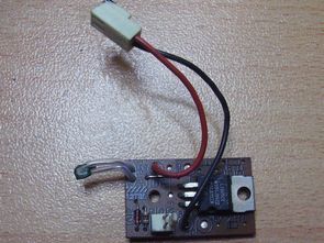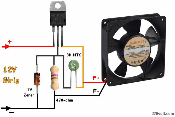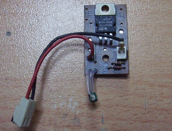
Occasionally some PC power supplies I’ve seen a different fan control circuit usually transistor circuits are used , but in this circuit 7805-5 volt positive regulator IC 1 7v zener 1 x 470 ohm resistor and 3k NTC used logic simple first voltage amplification phenomenon Let me tell you though 78xx , 79xx series and similar regulators known in anything but those who do not have the regulator in the chassis leg as a sort of setting end can be counted but only for an upgrade available so 7805 output zener or regular diode can be upgraded with , but not down- that’s logical fan -tested Meanwhile, thanks to 470ohm zener connected to the 5v output to be slightly higher outside the NTC is provided
Fan control circuit diagram used for;

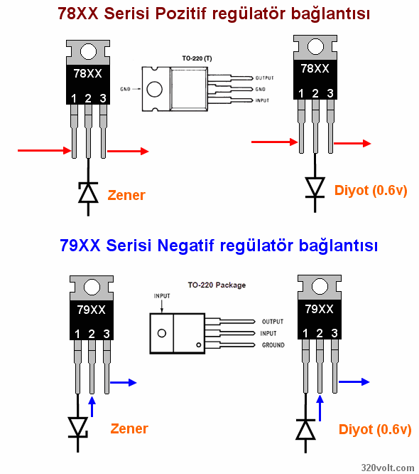
Voltage to upgrade zen and says connection diagrams below were given zener value until the upgrade can be done , for example 7812 12v output gives 3v zener is connected 15v output describes its diode is connected 0.6 volt is a rise diodes connected in series and the voltage can increase , for example 7805 5 volts gives 2 1N4001 series tied 6.2v you can get different names of the same nature as I said, can also be used in an integrated regulator I can not remember the last name 1.8v voltage regulator had an urgent need to upgrade upgrades have made with this method


Published: 2011/11/19 Tags: analog circuits projects, simple circuit projects
12V Fan Regulator Circuit Diagrams
Most of us know but do not know in people have computers in their boxes, power supplies or other parts used in the fan inside the tiny regulator circuit, usually SMD type of material used for these circuits into the fan at your leisure are deployed.
In simple understandable way, the fan motor control circuits, circuit diagrams are useful examples for expansions .. All fan control circuit overcurrent in the hall sensors, these sensors have been used for the key type.