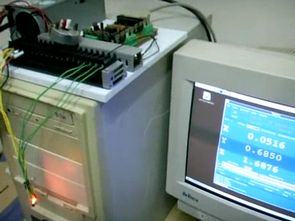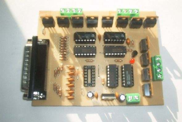
3 axis cnc (x axis, y axis and z axis) circuit computer’s LPT port is running through the old but sturdy and inexpensive system drive power on the floor MOSFET (irf9540, irfz44) used control section control section of the 74HC14, CD4013 integrated there. 3 axis cnc 30 volt 50 amp circuit’s 20 amp versions.

This is a simple 3-axis unipolar stepper board that can control stepper motors with 30VDC power supplies. The FET drivers are rated for 50A, but in practice this board should not be used anywhere near that current for motors. The power supply voltage, heat sinks, and cooling used for your particular application’s FETs play a very important role in making this determination.
The FET package is designed for 50 Watts of power consumption. If you are not familiar with electronics, the board should be built in stages and tested at each stage to eliminate problems.
Current Limiting Resistors (IMPORTANT)
When using a power supply higher than the motor’s rated voltage for a stepper motor, current limiting resistors are required. This board does not include space for current limiting resistors, as they can sometimes be quite large. The motor’s coil resistance can be calculated by dividing the rated voltage by the rated current. for example a motor rated at 5.2 volts @ 1.6 A (5.2/1.6) has a coil resistance of 3.25 ohms. To calculate the size of the current limiting resistor, subtract the motor voltage from the power supply voltage and divide by the current rating.
For example using a 12v power supply with the motor above (12-5.2/1.6), you will need a 4.25 ohm resistor. The wattage of this resistor is equal to the current squared times the resistance rating (1.6 * 1.6 * 4.25), or in this case, a minimum of 10.88 watts. The power resistors come in standard wattages or 1, 5, 10, 25, 50 watts.
Setting the Step Direction
JP1 through JP3 are the motor direction jumpers. JP1 is the Y axis, JP3 is the X axis, JP2 is the Z axis.
Optional Logic Probe: Often times a simple logic probe that gives a visual indication of a logic high or low condition is helpful in troubleshooting. Components R26, R27, R28, R30, T1 and LED2 make up the logic probe. By attaching a wire to the probe pad to use as an LED with the attached components, the test lead will light up slightly when the test lead is left open, becoming brighter when connected to a logic hi, it will not light up when a logic low is touched.
3 axis cnc pcb drawing of cards, schematic, layout plan has a list of materials Source: pminmo.com alternative link:
Şifre-Pass: 320volt.com
Published: 2011/06/15 Tags: motor control circuit, motor driver circuit
Stereo Class A Tone Control Circuit Transistor
Class A amp circuits are accustomed for some reason class a tone access control systems never occurred to me that been the performance I am very curious probably a normal tone control circuit based on is much better circuit critical materials 2SA872, 2SD666 transistors on the market Does not know, but there will not like, resistors 1% tolerance is used If the Class A quality solid capacitors and potentiometers think that the exact data