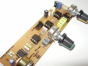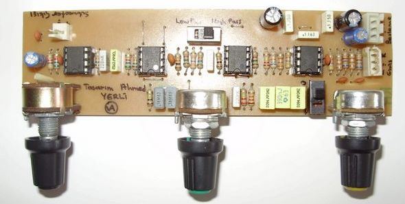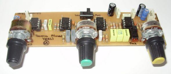
Circuit quality quite a crossover frequencies between 250Hz 25Hz circuit board on the opamp 4558 setting can be made. Proteus ares of project drawings are printed circuit boards. Subwoofer Crossover @ ahmedyerli of circuit and PCB design


About 25Hz to 250Hz Bass Crossover circuit;
Half-BASS AUDIO-FREQUENCY-PHASE HIGH BOOTS-PASS / LOW PASS settings can do. 25-250Hz Crossover published under the improved version of the circuit I have. Bass part is very effective, especially boots. If your amp speaker with a normal B switch this setting if you are trying amplified and filtered high pass crossover section comes into play.
Although the circuit raise the amount of noise has very low distortion rate. I’m completely design your own circuit. If you want a quality sound or bass would definitely recommend …
Subwoofer Crossover 25Hz to 250Hz proteus ares pcb file of the project:
Şifre-Pass: 320volt.com
Publication date: 2011/04/12 Tags: audio control circuits
TDA7294 Amplifier Circuit 2X100Watt
TDA7294 amplifier circuit design, as distinct from other solid power supply on a single PCB layout has a regular All inputs and outputs are via terminals. Proteus ares of project drawings are printed circuit boards. PCB design belongs to me.
TDA7294 is symmetric lowest 2x10v supply (+10 v-10v) and highest 2x40v (+40 v-40v) can be fed with dc.
olá estou precisando de um circuito igual a esse seu poderia me passar a senha por favor
olá, 320volt.com
Hey, I need PDF layout plz.
pcbpdf-pcb-region.rar
25hz-250hz-subwoofer-bass-crossover-pcb-bmp.rar