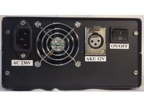
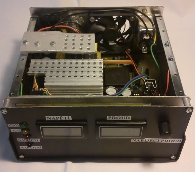
The designed SMPS charger system uses both constant current and constant voltage charging methods. It can be used to charge classic, gel and traction accumulators with a working voltage of 12 V. It can gently charge deeply discharged accumulators, but also maintain their maximum capacity during a longer shutdown. The charger is able to recognize the degree of discharge of the accumulator and, according to it, automatically choose the most suitable charging process. The individual charging phases are interpreted using light signaling and the achievable charging current is 20 A.
UC2906 circuit
Therefore, an integrated circuit from Texas Instruments UC2906 was selected and used. It combines all the mentioned requirements. In addition, it is adapted for continuous connection to the battery, which prevents self-discharge. For a better understanding of the function.
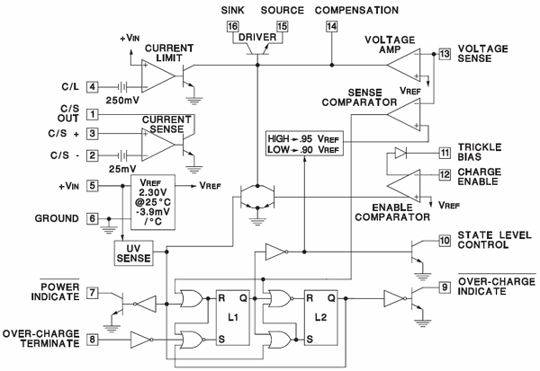
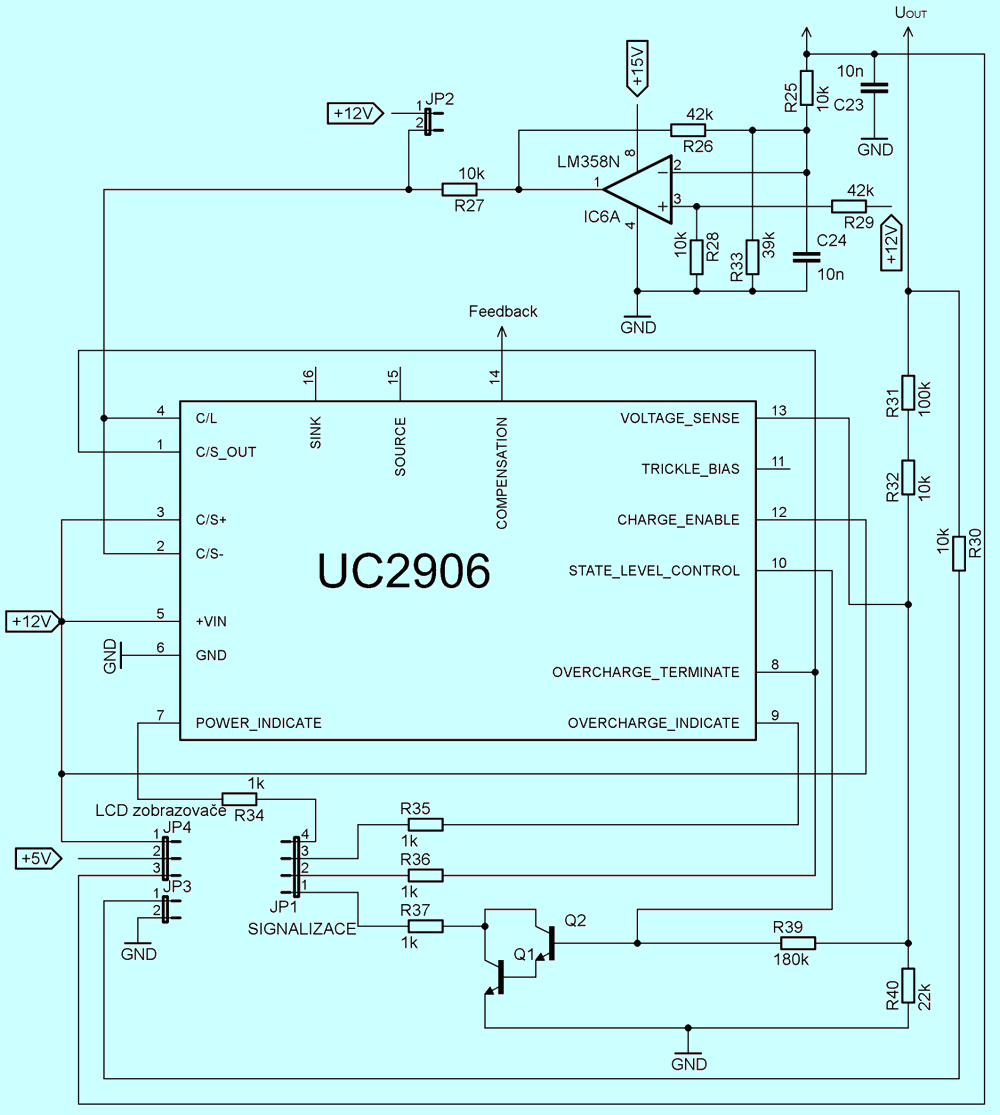
The circuit contains separate operational amplifiers that sense the voltage and current flowing into the battery being charged. Based on their status, the charging phase is evaluated and the circuit reacts to this by regulating the output current and voltage with the transistor.
However, this part of the first phase is not used in the charger itself, and charging takes place only when the terminal voltage of the accumulator reaches the value U1 = 12 V, which corresponds to 2 V per cell. At the moment when this value is reached, the circuit starts charging the accumulator with current INAB until the voltage U2 = 14.25 V appears on its terminals.
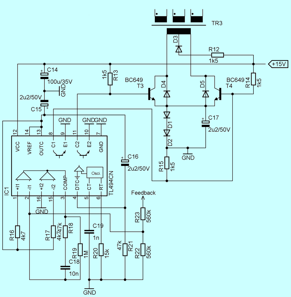
A significant amount of current flowing into their bases is required to switch them quickly, and without additional circuitry the TL494 circuit would not be able to supply that current. Transistors T3, T4 and excitation transformer TR3 are used to amplify it, which will ensure the necessary conversion of voltages and currents for the bases of power transistors.
Eagele Cad pcb, sch, etc. (transformer information pdf file page 18..21v) FILE DOWNLOAD LINK LIST (in TXT format): 26902b.zip rar pass. 320volt.com
Publication date: 2023/03/19 Tags: battery charger circuit, power electronic projects, smps circuits, tl494 circuit
Sir,
BRILLIANT circuit but……..what are the values of TRANSISTOR1 AND TRANSISTOR 2 IN THE FIRST SCHEMATIC?????
Thank you,
Dr.Chris
Hi,
Q1,Q2 BC546 A little more attention please. Review the document (pdf file part list page 32)
Good work.