12V Battery Charger for Current Limiting Lead Acid SLA (WET, MF, AGM and JEL). The battery charging circuit SLA uses a two-step process to charge the batteries. It automatically switches to float charge mode at a constant voltage after current-limited fast charging. Float charge: slow charge, floating charge, buffer charge etc. known as. Thanks to the float charging system in UPS devices, the batteries last for years.
Led lighting etc. repaired batteries in the Battery Repair Desulfator Circuit article. For this reason, the battery will be constantly charged. This circuit, which has a float charge feature, is necessary for a long battery life and can also be used as a backup system for modems or different devices.
The maximum charging current of the battery charging circuit is 1A. The LED indicates that the charger is in fast charging mode of the battery. When the LED turns off, the battery is charged and the charger is in float mode.
The current-limiting resistors, regulator, and heatsink will heat up when charging an empty battery. At 1A charging current the LM317 regulator will dissipate about 3 watts. The charging circuit must be well ventilated if installed in a box.
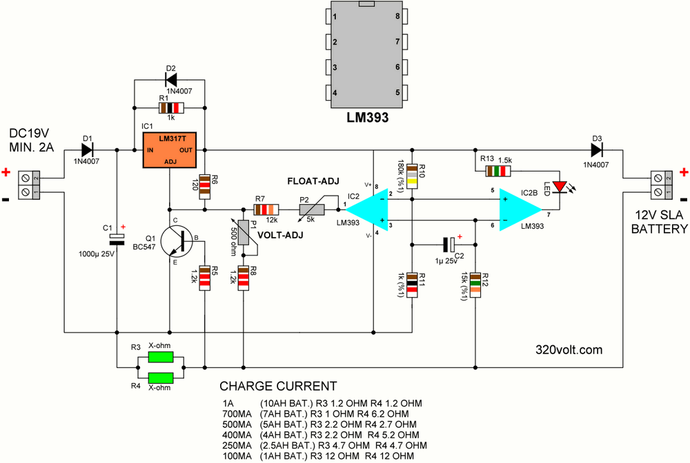
12v Battery Charger Circuit Diagram


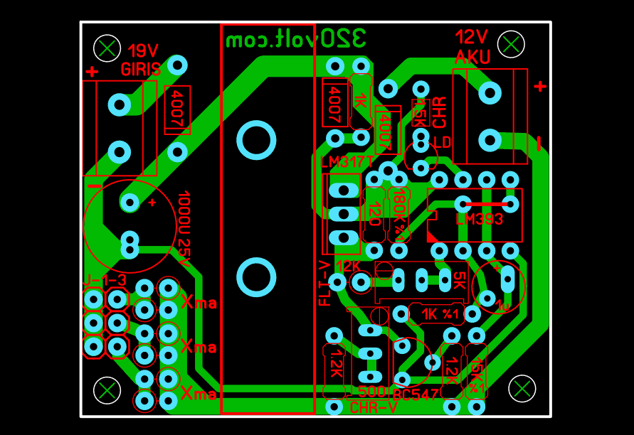
The PCB drawing was checked according to the schematic, I did not see any problems, but I did not print and test it.
The 12V battery has 6 cells. The following parameters were used for the charger:
1. The charging current should be about 0.1 times the battery capacity. Therefore, a 10Ah battery should be charged with 1A current (10 x 0.1 = 1). This helps prolong battery life.
2. Charge voltage 2.45V = 14.7V per cell
3. Float charge voltage 2.275V = 13.65V per cell
Battery Charger Circuit Operation
The power control of the charger is based on the LM317 adjustable voltage regulator. R6 120-ohm R8 1.2k resistors and P1 trimpot are used to adjust the charging voltage. It is necessary to disable IC2 (LM393) when adjusting the output voltage.
How does the current limit limit work? The current limit is determined by the resistors R3 and R4. The value of these resistors is calculated as follows:
R = 0.6V/I max
where 0.6V is the transistor turn-on voltage (nominal) R is the parallel connection value of resistors R3 and R4 I max is the charging current limit.
For 1A current, R = 0.6 ohms (0.6V/1A) so each resistor will be 1.2 ohms (1.2//1.2 = 0.6 ohm). When the resistors are connected in parallel, the value decreases. For a 0.6 ohm resistor, we use 2 x 1.2 ohm resistors in parallel. Also, the power of the resistor increases in parallel connection. When 2 0.25w (1/4 quarter w) resistors are connected in parallel, the total power becomes 0.50w (1/2 half w). .
If you want, you can use a single half-w resistor, but there is probably no half-w resistor in the calculated values. (Series, Parallel Resistor Calculation Page)
The transistor will open when the voltage drop reaches 0.6 volts. When the transistor is turned on it drops the voltage at the ADJ pin of the regulator and therefore the output voltage drops. As the output voltage drops, the circuit will “stabilize” to maintain the current limit.
What is the function of LM393? The LM393 is a Dual Voltage Comparator. The first comparator is used to set the float voltage, while the other (IC2B) is used to drive the charge indicator LED.
The voltage comparator compares the input voltage with a set reference voltage. The reference voltage is set by resistors R10 and R11. This reference voltage varies with the regulator output voltage. However, when the battery is charged below the current limit, the output voltage will be fixed and thus the reference voltage will also be fixed.
Voltage is the voltage across the current limit resistors (R3 and R4). This voltage is transmitted to the comparator through the resistor R12. Regulator for 14.7V battery charging voltage
output will be 15.4V (output 14.7v with 0.7v diode loss). The voltage divider uses the reference voltage on pins 2 and 5. (about 85mV)
The current required to cause an 85mV drop in the regulator output Current limiting resistors is ~142mA.
This means the battery is fully charged. The comparator IC2 output will drop. R7, R2 trimpot makes the R8 and P2 trimpots in parallel lower the total resistance and hence the regulator output voltage, which will be about 14.35 volts. There will be 0.7V loss on the D3 diode, the battery float charge voltage will be 13.65 volts.
LED lights up while the battery is charging. The LED will turn off when the charger is in float mode.
The power supply must have a minimum current of 2A and a voltage of 19VDC. Common adapters used with most laptops can be used.
Adjusting Output Voltage
Adjusting the output voltage is done when the LM393 is not plugged into the circuit. Connect a voltmeter to the battery charging terminals. Adjust the trimpot P1 until the voltage is 14.7 volts. Then cut the input voltage and plug the LM393 IC into the socket. Reconnect the input voltage and adjust trimpot P2 until the output voltage is 13.65v The charger is now ready to use.
Notes: In the 10AH battery charge (1A), the 1N4007 diodes at the input and output heat up a lot, but they did not fail, but it is more reasonable to use 2 amp diodes. I haven’t tried it, but with LM338K or parallel LM317 connection, higher capacity batteries can be charged. In this case, the larger cooler and current limiting resistor must be high in power, and the R10 and R11 resistors may need to be adjusted according to the current drawn by the battery when it is fully charged.
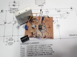
Battery Charging Circuit Test
Battery charging circuit gerber, pcb files 28107a.rar pass: 320volt.com
Source: kitsrus.com/pdf/K193.pdf
Publication date: 2022/02/27 Tags: battery charger circuit, power electronic projects
Dear Sir
Can i used LM338 in place of LM317 to increase current to charge 35A SLA battery ? Please advice
Thank you
Chris
Hi,
Yes you can use LM338K charge current 3.5a required for 35ah. TO220 case does not give 3.5a You should use LM338K T0-3 case
Current limiting resistor will be 5w and its value is 0.2ohm d1, d3 6A10
Dear Sir
Can i used this circuit recharge of my battery Capacity @ 20 HR: 145 Ah please tell me and
advice me
Thank you
Hi, the charging time is very long. Use a more powerful circuit
Hello sir,
Tell me can i use this circuit Battery model 12V 60AH.
https://ibb.co/PNyzfYp
Hello, With this circuit, the charging time will take a very long time. use LM338K change current limiting resistor circuit needs modification.
or use them; https://320volt.com/en/10ah-200ah-aku-sarj-devresi-buz11-cd4013/ 60w transformer usage
or https://320volt.com/en/intelligent-1ah-55ah-battery-charger-circuit-uc3906/