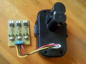
A simple battery balance circuit that you can use for balanced charging of series connected Lion, lipo batteries. Especially in 2 or 3 series connected batteries, balanced charging of batteries is of great importance. Battery groups used without a balance circuit can fail in a short time. Thanks to this circuit, this problem can be tolerated to a large extent.
Voltage limiter for charging Li-Ion and Li-Pol cells
A voltage limiter is a special circuit designed to improve the charging quality and thus extend the life of the batteries. Of course, we can also charge the battery pack without a limiter. However, its life will definitely be shorter. In addition, the danger of overcharging increases with the increasing number of series-charged batteries without a limiter.
a) protects the cell from overloading and thus destruction
b) allows charging a number of cells at once with a series connection without overcharging
c) can be used with any charger for Lixxx
d) can even be used to charge a battery with fewer cells than the charger is for
Basic technical parameters:
Limiting voltage: 4.20V; adjustable 4.1 – 4.3V
Current: max. 1A (up to 3A with good cooling)
Signaling: approx. 4 mA and above
Working principle
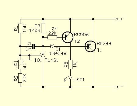
Li-Ion and Li-Pol batteries are very sensitive to overcharging. The maximum charge is determined by the size of the charge voltage – for all conventional cells it is 4.20 V. The limiter does not allow this voltage to increase and the “excess” charge current is converted into heat. An LED signals when the limiting voltage is reached.
Electrically, the limiter behaves almost like an ideal Zener diode.
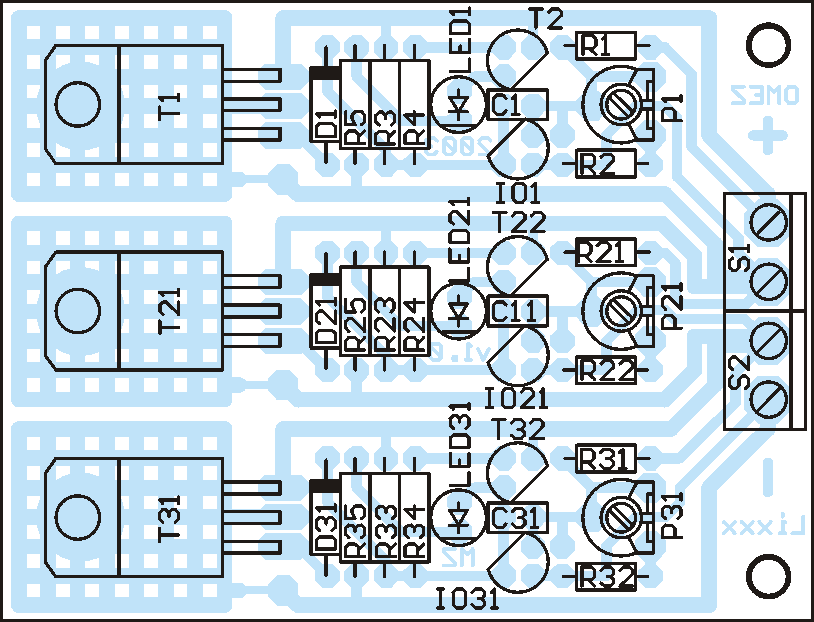
Parts list (blocks 2 and 3 are numbered 2x and 3x)
R1 – 15K (10K for LiFePO-3.6V cells)
R2 – 20K
R3 – 470R
R4 – 22K R5 –
1K
P1 – 5K
D1 – 1N4148
LED1 – Led3mm/2mA
C1 – 1n
T1 – BD244C
T2 – BC556
IO1 – TL431
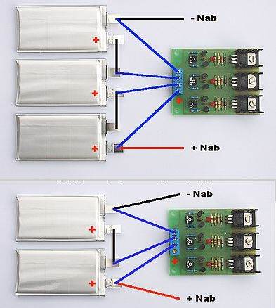
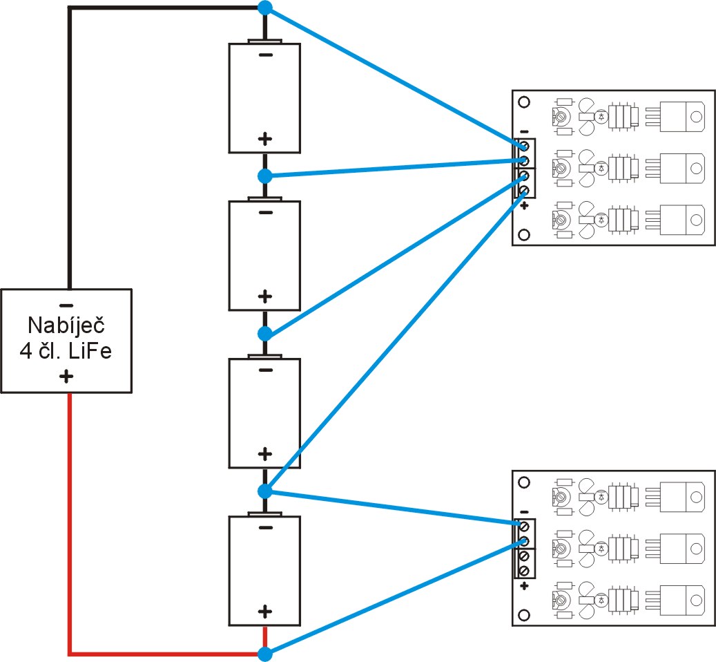
A series of cells should have internal connections between the cells. Then a limiter circuit is connected in parallel to each cell. The limiter is connected only during charging, preferably with an auxiliary connector, it is sufficient if it is sized for the maximum charging current or less. The length of the wires should be approximately 30 cm maximum. The polarity is marked on the circuit board. The limiter will not be damaged if the polarity is reversed.
Before starting charging, we connect the limiter to the cell group. Then we start charging. If everything is fine, the limiter does not affect the charging process in any way. The limiter LED can light up only at the final stage of charging, when the charging current is already small. If the charger is charged with a voltage lower than that set on the limiter, the LEDs may not light up even at the end of charging. This is true if the set is in order. Otherwise, it is more complicated.
Let’s assume that a discharged set is being charged. The earlier some limiting diodes light up from the beginning of charging, the greater the difference between the cells, signaling some change in the cell parameters. When charging at full current (up to about 2/3 of the total charging time), signaling should never occur in phase. And certainly not immediately after charging. In both cases, we immediately stop charging and analyze the cause. It can be a completely faulty cell or a cell with a low capacity. For a set of parallel-connected cells, it will be necessary to disconnect the parallel cells and find the faulty cell. The suspicious cell will most likely have a different voltage than the others, even when it is idle.
Theoretically, it would be possible to continue charging, but in practice there is no point in this, because without finding the cause, the set will continue to deteriorate faster with further use. Thermal overload of the limiter can also occur at high charging currents. If we are not sure about the state of the set, we first charge it with a lower current!
Limiter settings
Finished limiters are delivered set to 4.20V. In some cases, it is advisable to set the limiter differently. Since these are already quite accurate values, it is also necessary to take into account the accuracy of common multimeters.
It is ideal for the charger to charge to exactly the same voltage as the limiter is set to. In the case of a charger with an adjustable output voltage (e.g. MZ), we set the output voltage of the charger so that the limiting diodes start to burn out immediately or just before this point – without a battery.
For example, if we have a charger that charges up to 4.15V and we cannot change it, it is recommended to set the limiter to 4.15V or preferably 4.16V. Attention, some processor chargers do not measure the voltage very accurately. In the case of processor chargers, it is necessary to check whether the charging is terminated correctly even with the connected limiter. The behavior of these chargers is determined by the program and may differ for different types.
We will set the limiter as follows: set the stabilized source in the laboratory to about 6 V and the current limit to 10 – 50 mA. We connect a limiter block to the source, the LED lights up and we set the required voltage with the trimmer. If we do not have a laboratory source with current limiting, we can use a source or an accumulator with a voltage of 12V. One block of the limiter we set is connected to a 12V/50mA bulb (ve.g. 12V/1.2W) to the source.
We measure the voltage with the tips of the multimeter directly at the limiter terminals – not at the source. The important thing is that we must set all three blocks to exactly the same voltage. If we change the limiter to a different voltage, we must re-set all the blocks. Of course, this also applies to multi-cell banks, where several 3-block limiters are used in series.
Cooling
In normal operation, when there is only fine-tuning of individual cells in the final phase of charging, the power loss of the limiting transistors is small. Only in the event of a serious fault (outage, large loss of capacity) in one of the cells of the bank can a larger current pass through the limiter. The provided coolers can provide heat dissipation up to a current of about 1A.
If we assume that defective cells occur during use and use a larger charging current, it is necessary to use a larger cooler or forced cooling. Then we mount the transistors on insulating pads on a common cooler. The maximum current of a well-cooled limiter is about 3 A. When installing the limiter in the box, it is advisable to remember about good cooling.
Limiter as an active voltage divider
The limiter can be used even if we have a charger for three cells and only need to charge one or two cells. We connect the limiter to the output of the charger and connect only one or two cells to the terminals of the limiter. The limiter block, which will not have any connected cells, will reduce the voltage for the other cells. This method is only suitable for a smaller current, because it has an energy disadvantage – the energy of the disconnected cells is converted into heat. In this case, the limiter must constantly withstand the maximum charging current. With the supplied limiter, it is about 0.70 A. For a larger current, it is necessary to use a larger cooler or forced cooling with a fan.
However, this method is very convenient for measuring and shaping objects. In most cases, one three-cell charger and one limiter will be sufficient.
Do I have to use the limiter every time I charge?
The decisive factor for using a limiter is the pairing of the articles. If all cells were exactly the same and their parameters did not change over time, there would be no need to use a limiter. The reason for using a limiter is to charge each cell to 100% without having to charge each cell individually. It also serves as a partial protective element. The more series-connected cells there are in the set, the more important it is to use a limiter. Abroad, the name “Li-pol balancer” is used.
Some cells need to be compared only after a few cycles, some already during the first charge. Therefore, we often check the voltage of individual cells in the discharged and charged state. If the deviations between the cells are greater than a few hundredths of a volt, the cells need to be compared. Using a limiter will increase the quality and safety of charging and extend the life of Lixxx batteries.
Why can’t the limiter be permanently connected to the batteries?
In order to be permanently connected, the limiter must have as little consumption as possible in the inactive state. Technically, there is no problem and the components with the necessary parameters (mainly the ref. voltage source) are there. The problem is their price. So big that the price of the limiter would be at least 3 times higher. Another problem is what to do with the weight and especially the excess heat. So even the maximum current cannot be very large. The coolers are large and heavy, and the heat source directly in the battery is not ideal. Protection circuits in series with the cells are not yet possible, because any semiconductor component worsens the internal resistance of the accumulators, which is one of the very important parameters when used for propulsion.
source http://www.zajic.cz/omezovac/omezovac.htm
Published: 2010/11/30 Tags: battery charger circuit, power electronic projects, simple circuit projects
AVR Experiments Boards
For people dealing with Atmel AVR programming in tests of various modules that can be used in experiments (avr matrix, avr keyboard, avr buttons, avr lcd display, avr dipswitch, avr led bar) circuits pcb circuit belonging to the schema files have.