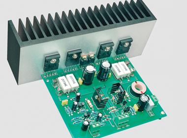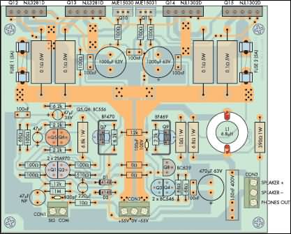
The supply voltage of the Ultra LD 200W Power Amp is symmetrical +55v -55v total 110 volts dc. Be careful. The best thing in the circuit is that there is no need to adjust the quietness, you know, there is this setting in a multi-transistor amplifier, it is always confusing, right? is it normal ? Is the temperature high setting wrong? etc.
In addition, voltage values of certain regions are given on the diagram.
200W Power Amplifier Module
This new amplifier module replaces the Power module described in the April 1996 issue and the Ultra-LD module presented in the March 2000 issue. It produces high power at very low distortions. In fact, as far as we are aware, it is the lowest distortion class AB amplifier ever released.
Features and performance
Output Power: 4ohm 200 watts RMS 8ohm 135 watts RMS
Frequency Response at 1W: -3dB at 4Hz, -1dB at 50kHz
Input Sensitivity: 1.26V RMS for 135W to 8W
Input Impedance: ~ 12kW
Nominal Harmonic Distortion: < 208% to 20kHz for 8W operation; typically < .001% )
Signal-to-Noise Ratio: Unweighted 122dB vs. 8W (22Hz – 22kHz) vs. 135W
Damping Factor: < 170, relative to 8W at 100Hz; < 50 at 10kHz

Figure 1: Circuit uses new Thermal Trak power transistors (NJL3281D, NJL1302D) from On Semiconductor. These transistors also have an integral diode used to control the quiescent in the Class-output stage. The four diodes are shown separately in this circuit (i.e. DQ12, DQ13, DQ14 and DQ15) for clarity, but in reality they are a whole with the output transistors having five jumpers instead of three. Note that the various voltages marked on the circuit will vary with the supply rails.
It has Thermal Trak transistors, MJL3281A and MJL1302A integrated diode. As a result, the circuit does not need a quiescent current setting or a “Vbe multiplier” transistor.
This is also our first amplifier module to use a double-sided PC board. There seems to be no reason to use a double sided board for a relatively simple circuit like this, especially since our previous single sided amplifier boards had few connections. In fact, we used the double-sided design to improve and simplify the external wiring to the PCB board arranged to substantially cancel the magnetic fields produced by the asymmetrical currents drawn by each half of the class B output stage.
The power output of the new module is the same as the Plastic Power module mentioned above and is significantly higher than the original Ultra-LD module. It also uses a much simpler power supply than the Ultra-LD module.
Power output is 135 watts RMS at an 8 ohm load and 200 watts at a 4 ohm load for a typical harmonic distortion below 0.001%. The new module has a slightly higher gain than the Ultra-LD module but still manages to produce an improved -122dB (unweighted) signal-to-noise ratio over 8W up to 135W. It is extremely quiet.
Source: www.siliconchip.com.au/cms/A_110797/article.html
Ultra-LD 200W Power Amplifier PCB schematic alternatfi link:
Şifre-Pass: 320volt.com
Publication date: 2008/09/03 Tags: audio amplifier circuits, transistor amplifier
Video Enhancer Circuit with TDA9181 Comb Filter
Video Enhancer Circuit 9 volts AC supply voltage regulator circuit on the S-video, Composite video out there