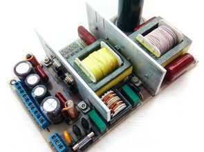
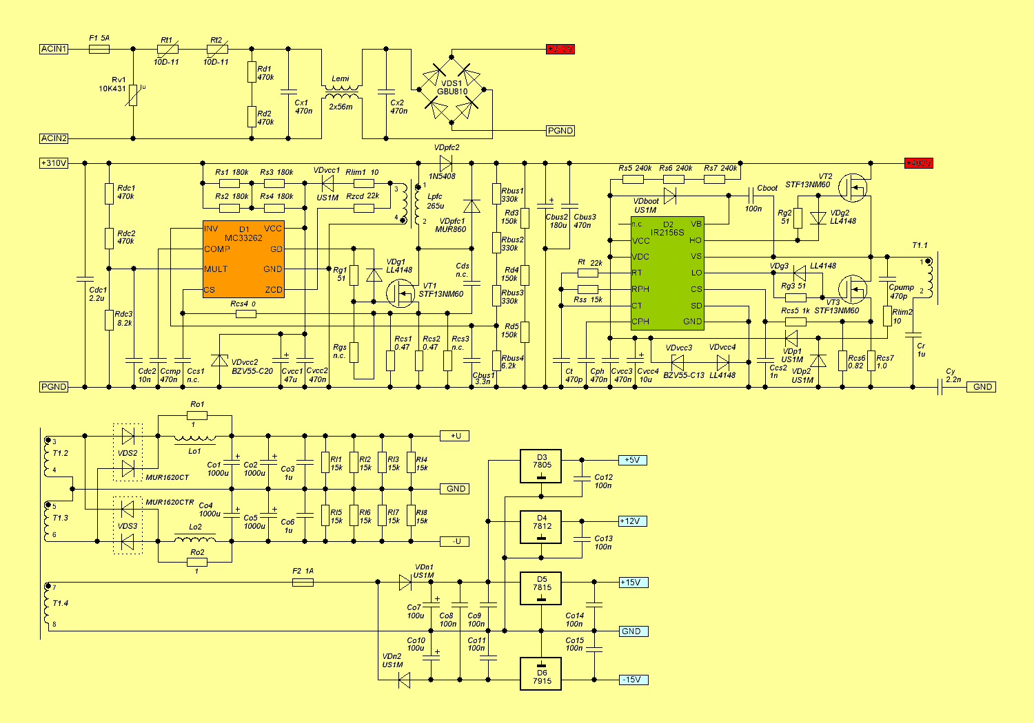
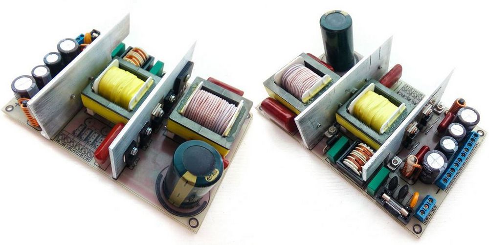
Active PFC supported SMPS power supply is made with IR2156 Ballast driver integrated circuit. Active PFC section uses MC33262 active power factor integrated circuit. Output voltage of SMPS circuit on load is 2X40VDC PFC output voltage is 400V
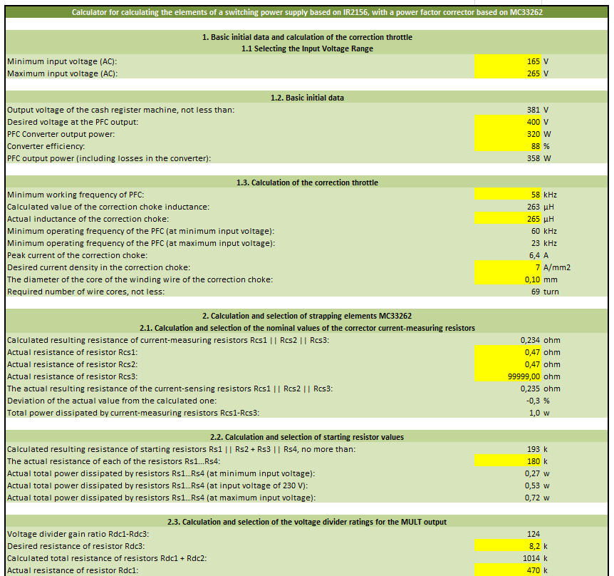
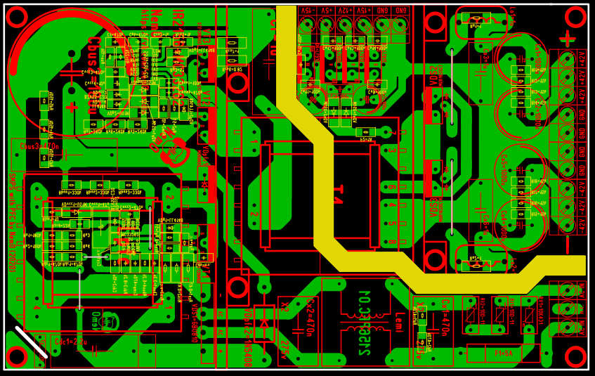
There is source PCB drawing of Active PFC Power supply project (sprint layout 6) also MC33262 PFC Coil calculation frequency calculation, voltage etc. and for IR2156 in the same way transformer, protection, voltage detection, frequency resistances etc. Excel program is also given for IR2156 calculations.
MC33262 Pinout;
1. Feedback Input – inverting input of the error amplifier. A feedback circuit is connected to this pin, which is used to monitor, adjust and hold the output voltage of the power factor corrector. The threshold voltage of the error amplifier is 2.5 +/- 0.035 V.
2. Compensation – a pin directly connected to the output of the MC33262 error amplifier, designed to connect an external frequency response correction circuit of the error amplifier; necessary to protect the latter from self-excitation.
3. Multiplier Input – output to which a pulsating voltage is supplied from the output of the network rectifier. Thus, the MC33262 receives information about the instantaneous phase value of the network voltage and the magnitude of the input voltage.
4. Current Sensing Input – a pin used to control the amount of current flowing through the power switch.
5. Zero Current Sensing Input – zero current sensor input. This output is supplied (through a resistor) with the voltage from the secondary winding of the smoothing inductor, which is necessary to determine the moment when the energy transfer cycle to the load is complete (the current through the smoothing inductor is zero).
6. GND – MC33262 common pin.
7. Driver Output
8. Vcc – MC33262 supply pin.
2X40VDC SMPS Circuit Diagram
About IR2156
Only about 200 μA is required to start the IR2156 IC, which means that no additional power supply is required for its operation (the IR2156 is started via a resistor and then powered from the power supply circuit)
Built-in high-voltage driver. The IR2156 (unlike, for example, the TL494 and SG3525) has a built-in high-voltage driver, so there is no need to use another additional driver chip or an isolation gate transformer;
Programmable generator. The IR2156 allows you to set the required operating frequency, frequency and operating time, as well as the amount of dead time, in preheating mode (soft start mode) with the help of external elements
Preheating. In lamp ballasts, this function is necessary to preheat the low-voltage lamp electrodes before ignition (to reduce the ignition voltage and extend the lamp life). Preheating will perform the function of limiting the starting current, i.e. the soft start function.
Overload and short-circuit protection. In case of overload or short circuit at the output of the power supply, the operation of the IR2156 generator (and subsequently the entire power supply) is stopped immediately. The IR2156 generator and driver are inactive and the protection remains until the IR2156 supply voltage is reset
Protection against low input mains voltage. This function of the IR2156 protects the device from low input voltage. The protection is activated when the input mains voltage and therefore the dependent voltage on the supply high voltage DC bus falls below a preset threshold value.
The IR2156 integrated circuit also has an SD. pin for protection. In case of overheating or DC output problems, this pin can be triggered to put the IR2156 into UVLO (Undervoltage-lockout) mode.
Şifre-Pass: 320volt.com
Source: cxem.net/pitanie/5-397.php
Publication date: 2024/12/17 Tags: power electronic projects, smps circuits, smps projects, smps schematic