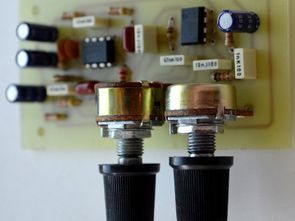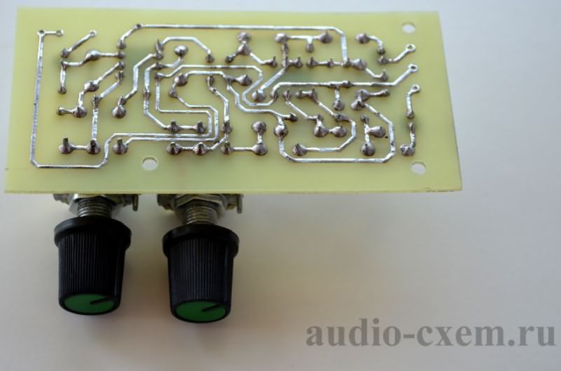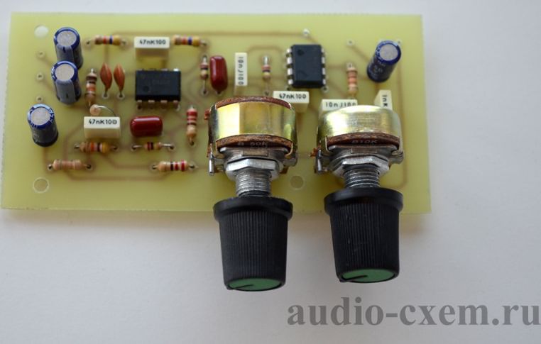
The subwoofer filter, or low-pass filter, is designed to suppress high frequencies that shouldn’t be fed into the audio amplifier’s input and then into the low-frequency head (woofer, subwoofer). The subwoofer filter has a cutoff frequency. A signal input to the filter with a frequency greater than the cutoff frequency will be attenuated. These signals are not found at the output of the Filter.
In addition, the subwoofer filter circuit has phase angle adjustment. The filter itself (like other low-pass filters) shifts the signal by a certain angle, so if you turn on the subwoofer and additional acoustics (bypassing the filter), the signals at the outputs will differ by a certain angle.
Key Specifications of Subwoofer Filter
Supply voltage: +9-15V
Current consumption: <10mA Cutoff frequency: 50-200Hz Signal attenuation (at 1kHz frequency) 40dB
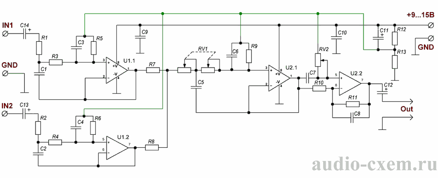
Subwoofer active filter circuit diagram

Subwoofer active filter material list
U1,U2 – TL072, TL082, NE5532
R1-R4 – 47 … 51 kOhm
R5, R6, R9 – 270 kOhm
R7, R8 – 220 Ohm
R10, R12, R13 – 10 kOhm
R11 – 12..13 kOhm
RV1 – 30-50 kOhm (6 st.)
RV2 – 10 kOhm (3 mono)
C1,C2,C6 – 0.047uF (film)
C3,C4 – 0.022 uF (film)
C5,C7 – 0.01uF (film)
C8 – 0.001uF (film)
C9,C10 – 0.1uF (ceramik)
C11-C14 – 22uF 16V.
All resistors are 0.25W


The U1.1 and U1.2 elements have a collector that optimizes the operation of the low-pass filter when a stereo signal is applied to its input. Adjustment of the phase shift angle is performed with the subwoofer filter, the over-ear speaker system turned on. If a two-channel oscilloscope and a generator are available, more precise settings can be made using these.
Source: audio-cxem.ru/shemyi/regulyatoria/filtr-sabvufera.html
Alternative for source PCB file prepared with Sprint layout 6;
Şifre-Pass: 320volt.com
Publication date: 2022/09/24 Tags: audio control circuits
Please could you leave a list, of all the IC’s. from u1.1/u1.2/u2.1/u2.2
is this a 4th order low pass filter? i want to build diy 4th order low pass filter for active subwoofer. which can i build. thank you. please provide pdf