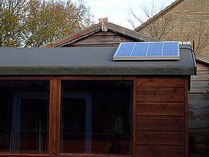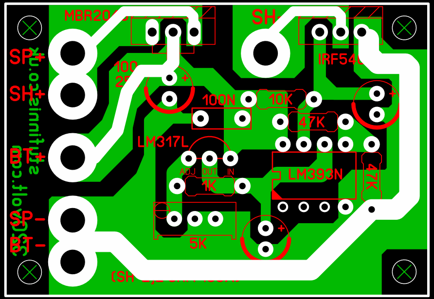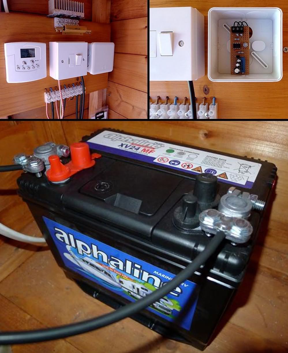
The 40 watt panel with solar energy system has been used for years and has never caused any problems. A simple circuit made with LM393 integrated circuit is used for battery charging and solar charge regulator.
The battery used in solar energy system is called deep cycle or leisure battery. It can handle over-discharging compared to a normal car battery that needs to be constantly charged by the alternator, like in vehicles.
The theory behind charging lead acid batteries is very complex, but a simple rule to prevent cell damage is to not let the voltage drop above 14.4V during charging or below 11V during discharge; the ideal charge voltage is around 13.5V. Systems can be used that disconnect the battery if the voltage drops too low, but if you know the daily demand and stay within that, there should be no problem.
Commercially produced units have different prices, features and current usage, but if you want to build your own, the simplest method is to use a shunt regulator. Shunt regulators may not be as efficient as processor-controlled designs, but they work very well.
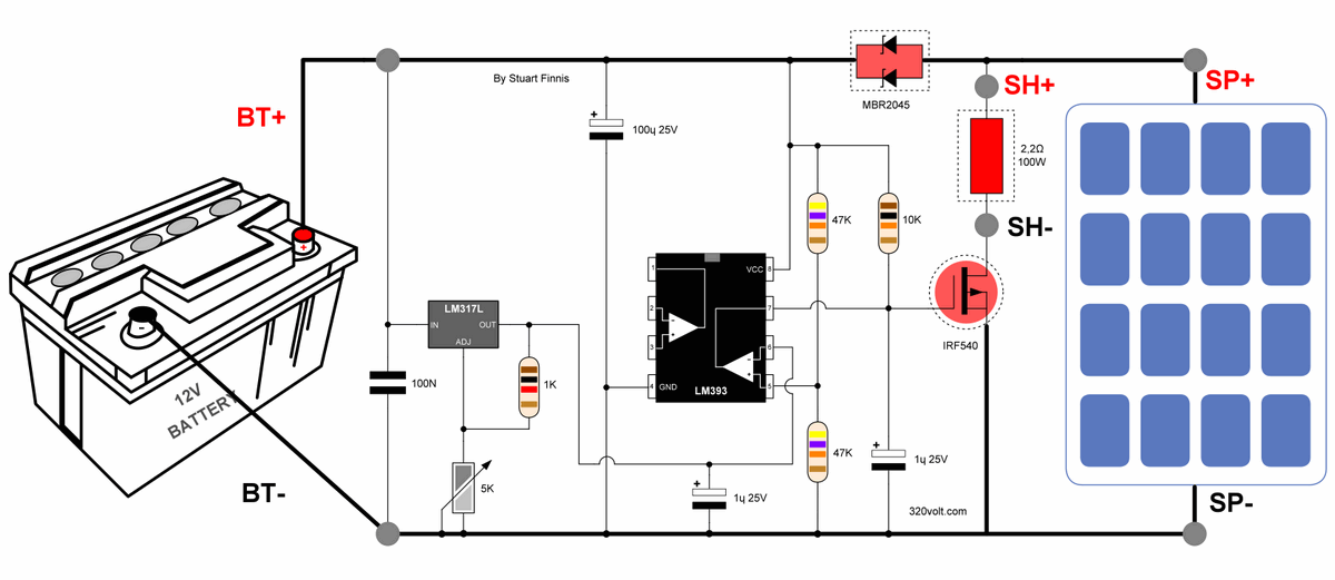
The circuit also uses the LM393N voltage comparator, but the output is different. When the + input is lower than the – input, the output (pin 7) will be grounded internally, effectively tying the gate of the IRF540A MOSFET and the lower end of the 10K resistor to ground. However, when the + input is higher than the – input, the output opens the gate, allowing the 10K resistor to power the gate. An important feature of the LM393N is its low current consumption. The entire charger circuit draws only about 3.5 mA.

The inverting input (pin 6) is fed from the LM317L regulator, the output voltage is set by the multi-turn preset VR1. The non-inverting input (pin 5) samples the voltage across the battery through a voltage divider formed by two 47K resistors.
Since these resistors are equal in value, the voltage at pin 5 will always be half the battery voltage, no matter what. This is accomplished by adjusting VR1 to give half the required charging voltage at pin 6 (e.g. 6.7V for a desired charge of 13.4V).
The formula for calculating the LM317L output voltage is: Vout = VR1 value ÷ 1000 + 1 x 1.25. With the values used, this equals 1.25 to 7.5 volts available at pin 6 of the opamp. Now if the battery voltage is below 13.4 volts, pin 5 will be less than 6.7 volts, and thus the output of the comparator (pin 7) will be grounded and the MOSFET will be off.
The solar panel will be connected to the battery and will be charging. As the battery charges, its voltage will rise to 13.4 volts, at which point pin 5 will also rise, eventually reaching 6.7 volts (the comparator inputs always want to balance). Because of the extremely high gain of the IC, pin 5 needs to be a measurably small amount higher than pin 6 to make the output (pin 7) open circuit, which will allow the 10K resistor to open and connect the MOSFET.
2R2 effectively transfers its energy to a resistive load instead of the battery by using a ‘shunt’ resistor across the solar panel. This keeps the voltage across the battery at a predetermined level. Note: In practice and sun permitting, the setup can be easier and more accurate by simply connecting the solar panel without the battery or load, and then setting VR1 diagonally to 13.4V.

It is a 16 amp Schottky diode that prevents the battery from being shunted by the 2R2 resistor. It also stops the voltage from the battery being fed back into the panel, although most panels have a built-in protection diode. This component is not critical as long as it can handle the current.
Normal silicon diodes can be used, but the Schottky types are better because they have a lower voltage drop across them, so less energy is lost. The IRF540A MOSFET is rated at over 20 amps, which means that the circuit should be able to handle the relatively low amount of power demanded of it quite easily, but the high current components still need to be mounted on a heat sink.
The 2R2 resistor on the 40 watt solar panel used got extremely hot, so it is recommended to use at least a 100 watt resistor. If you use a lower power resistor, you can use a fan or a heat sink. In fact, a 12V fog light bulb could be used, but no alternatives are mentioned.

Şifre-Pass: 320volt.com
source: stufinnis.co.uk/solarproject.html
Publication date: 2024/12/17 Tags: battery charger circuit, power electronic projects