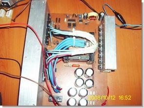
DC DC Converter Circuit is based on sg3525 smps control IC, it can provide 900w power. The power transformer used is etd59 output 4n25, isolated with opto coupler, it gives a symmetrical + – 70 volts total 140 volts output with 12 volts. There is a pcb file prepared with ares that can be used as an auto amplifier supply.
symmetric 70v complete DC DC Converter


CAUTION Be careful is working with high voltage capacitor circuit connections Beware + – If you connect the high voltage polarity may be large explosions before running the insured Power Line circuit, protective goggles
SG3525 DC DC Converter Circuit proteus ares PCB files:
12V to 70V DC DC Converter Circuit SG3525 900W
Şifre-Pass: 320volt.com
Publication date: 2009/01/27 Tags: dc dc converter circuit, power electronic projects, sg3525 circuit
PIC16F628 Multi-Mode Encoder, Counter Circuits CCS C
Hello friends, I have done well to share with you the counter circuits as functions istedim.kısa tell. There are three mode of counter:
enc: millimeter accuracy in the measurement is made. The value is set in the output data.
Counter: Counts the amount is set at the value of the output data.
disp: Meter makes measurement, shows decimeter accuracy
You can connect to the encoder input, interrupt b0 rises from 0 to 1 at the moment in a direction B output is 0 if one is going in the other direction. I do not know, but these commands can be prepared from the PLC logic business benefits
Please send me the pcb layout
inside pcb zip file (900w SMPS.LYT proteus ares pcb file)
Hi
Only PCB layout file no schematic. Please share
no its not supported please send pdf to my mail
pdf and gerber; pdfgbr.rar
How many layers this pcb bruh?
In jlcpcb its detected 4 layers. Is it true??
Hi, pcb is single layer.
Thank so much bother..
God bless you🙏
Hello sir…
Is this gerber file 4 layer or 2 layers??
I’ve try to see the file on jlcpcb it saying 4 layers.
Please help
For R10K from mosfet. Is it connected to red wire jumper or not sir. Thanks before
https://ibb.co.com/8xXyc8s
sir should i take print directly or at what magnification(zoom) level i should take the print
print directly
https://ibb.co.com/mtw1WYy
Really sorry brother. Got trouble with internet connection and double post.
For R10K from mosfet, it is connected to red wire cable jumper or not bruh??
Thanks so much before
yes that’s true
Hi is it dual? +70 – 70?
Hi,
yes dual
Give me the password please sir🙏🙏🙏
Hi,
pass: 320volt.com
There is a password on the fil?! Plzz
I wana us this circuit to activat an inverter frige compresor or a washing machine motor from a car battery what do u think?
Send me the password plz
Hi . Please email me the details of the etd59 transformer and filter coil
1- The number of wires,
2- Number of rounds,
3- Wire thickness,
Thanks
Hello,
http://www.elisanet.fi/ch/fbsmps12v.html
You can use the online calculation tool at the end of the article.
Unfortunately, I did not understand the number of turns, the number of wires, the thickness of the wire, the type of core, and the number of wires for the transformer circuit. Please, if possible, introduce a better reference for guidance. Is there a ready sample of trans by part number?
Hi Please guide the specifications of the number of turns of the wire, the thickness of the wire and the diameter of the bobbin filter core in the circuit
Hi,
Core ETD59
Secondary, output winding will be connected in parallel with 4 pieces of 0.9mm wire and will be wound 2×20 turns.
The primary winding will be connected in parallel with 9 pieces of 0.9mm wire and 2×3 turns of winding will be made.
Example transformer winding method