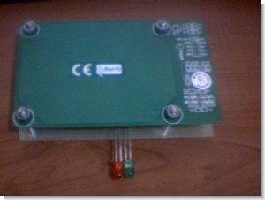
Hi friends I have done with you I share a RF-id application. Application for educational purposes only and is exemplary and is capable of being improved. If we are talking PIC16F88 application is used as a controller. Located in the market comfortable with PIC16F88 PIC16F628 16F628 not much difference in price than `is a handy controller.
RF-ID circuit diagram
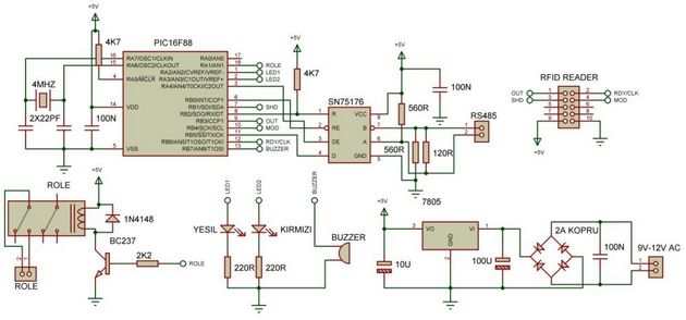
The so-called circuit 125KHz EM4100 RF-ID card read read and sends the data series. RS485 communication circuit on the printed circuit are wanting to cancel and use it as RS232. Read circuit for 5 seconds after you send the card information, waits for information from the answer the answer is ‘E’ green LED light buzzer and relay runs for 1 second. A different answer or a reply is not received for 5 seconds to cut the red LED and buzzer twice as warning. There are two LEDs on the circuit buzzer and relay.
Also read on your pc and send a reply to the received code with delphi 7 I made a small interface circuit can test it. CCS is written in C code for PIC16F88.
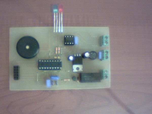
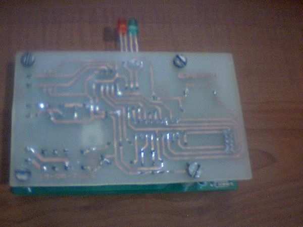
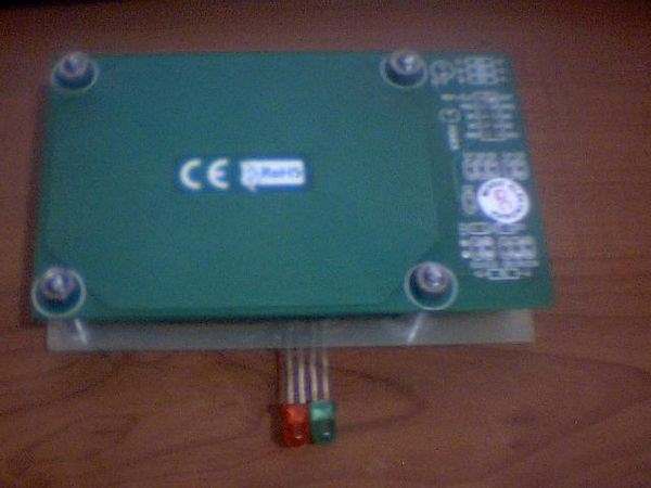
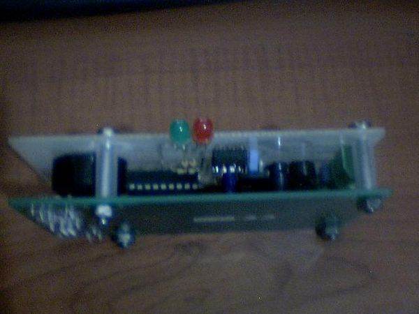
Finally, the on-board RFID reader module is a module for microelectronics. Domestic or abroad, can be obtained. En EM4095 chip on the module. Wishing to be helpful.
PIC16F88 SN75176 CCS C EM4100 RF-ID Reader Project Proteus isis schematic pcb CCS C RF-ID Source code files:
Şifre-Pass: 320volt.com
Published: 2009/10/25 Tags: microchip projects, microcontroller projects, pic16f88 projects
USB UART Converter PIC16F88 Circuit Attiny2313
Recently circuit on the web I’ve seen perform this southern been applying If we are talking application atmel’s famous ATtiny2313 achieves with USB UART converter further circuit 8bit I / O 128-byte EEPROM 32-byte FIFO buffer a lot as have the ability to detailed information AVR309 application note exists in the circuit did and it works just fine.