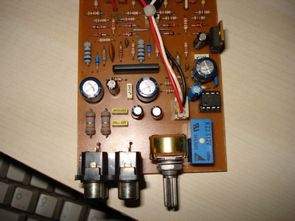
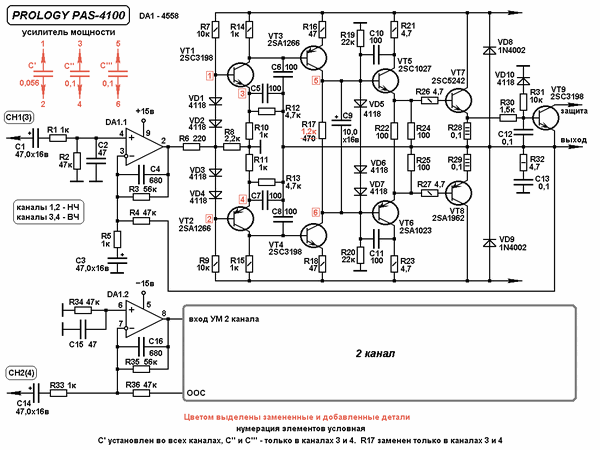
BJT transistor circuit description of a quality amp circuit diagram pcb’s drawings. Prepared persons (author unknown a circuit in the archive) thanks the following descriptions are his own.
Drive transistors. BC548C instead of 2SC3198 (BC237), instead of 2SA1266 BC558C (BC307C) can use. Output transistors from low to high, depending on the supply voltage TIP3055-TIP2955, BD911-BD912,-2SB688 2SD718, 2SC5200-2SA1943, BD249C-BD250C be used as a conjugate. Circuit of the original supply voltage + / – 35V CAR POWER AMP and PAS-4100. 2 channel has been designed by me.
2-channel and 4-channel as a tried and used in front of a crystal-clear sound seamlessly with LPF performance was solid. .2 X 220W 18V transformer with a 4 channel version without fainting and cut me personally was pleased. 8 bridge diode, the + and – ends of two pieces is enough to feed 3,300 Mf 50V capacitor. As shown in scheme-1 4558 (SIP9 casing) to which a rare TA755558S was used instead.
About the circuit;
Driver tr. Instead of 2SC3198, you can use BC548C ( BC237 ), instead of 2SA1266, you can use BC558C ( BC307C ).
Output transistors can be easily used as TIP3055-TIP2955, BD911-BD912, 2SD718-2SB688, 2SC5200-2SA1943, BD249C-BD250C equivalents, depending on the supply voltage.
The original supply voltage of the circuit is +/- 35V and PAS-4100 CAR POWER AMP. It was designed by me as 2 channels.
It has been tested as 2 channels and 4 channels, and it has exhibited a crystal clear sound and a flawless performance with the LPF stage used in front.
.2 x 18V 220W transformer with 4 channel version has pleased me without stalling and cutting.
8A bridge diode, two 3300 Mf 50V capacitors at + and – ends are sufficient for feeding.
DA-1 4558 (SIP9 case) shown in the diagram is rare so TA755558S is used instead.
100W Amplifier Circuit the finished
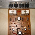
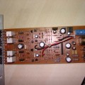
As shown on the picture and pcb, the 3 pin pcb female con. (Delay In) on the back of the relay will be soldered to the ends on both channels, the R and L ends will be soldered to the output line, and the G end (middle end) will be soldered to the GND line. It is a 10-number circuit in terms of cost-performance and I recommend it.
Important: As shown in the diagram, pins 4 and 6 are drawn as + inputs. However, since a careful eye is required, it is shown as if it will be connected via pin 7 in the diagram. (Unfortunately, these people are deliberately sending small incorrect drawings because they are after financial size. The truth is that pins 4 and 6 are given to the signal input as + input ends, and pins 3 and 7 are given to the gnd line as R+C input ends.)
The cut-off frequency of the second-order low-pass filter can be adjusted between 40 and 160 Hz. This is a great option for a subwoofer, but the range is clearly small for mid-bass.
The cut-off frequency of the variable order high-pass filter can be adjusted from 60 to 1200 Hz. Too low for a tweeter, too wide for a midrange. Since the cut-off frequency of the fixed 2nd order coupling is around 70 Hz, the quality factor and slope change significantly during adjustment.
Set the upper limit of the low-pass filter adjustment range to 500-600 Hz. This is quite sufficient to combine the bass band with both the diffuser and dome midrange heads.
Reduce the adjustment range of the high-pass filter to 600 Hz and increase the cut-off frequency of the fixed coupling to 180 Hz. The steepness of the frequency response in the region below 200 Hz will remain constant – 18 dB / oct.
Express PCB and other files of the amplifier circuit;
Şifre-Pass: 320volt.com
Published: 2010/11/28 Tags: audio amplifier circuits, transistor amplifier
Ceiling Light Led Lamp Power SMD Led
Ligh circuit 15 SMD LED lamp circuit with almost 20w led ceiling lamp to light up their halogenated gives 12v dc operating voltage of the circuit 100ohm resistor used for current limiting lamp power 1.8watt
SMD LED lamp and compare their halogenated official Led lamp circuit of lab prepared with eagle pcb, schema files have.