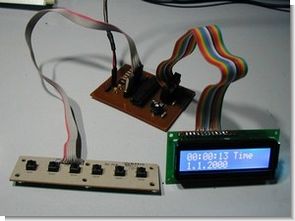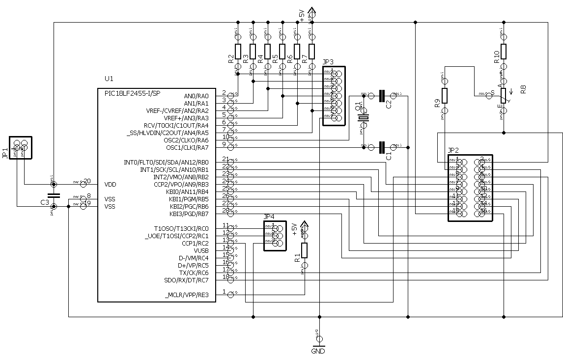
The circuit is based on pic18f2455 with 2×16 lcd (hd44780) and it displays the date and time. There are source c and other header files prepared on mplab ide, there are also schematics and pcb files prepared with eagle. It is a good resource for people who do programming with c language.
PIC 18F2455 LCD clock This circuit for an LCD clock with a 16×2 dot matrix LCD display is implemented with a PIC18F2455 based alarm and calendar and just a few components. The display is connected to JP2. HD44780 is a compatible display.

LCD Clock Material list:
R1-R7 Pull-up resistors 10kOhm
C1, C2 22pF ceramic capacitors
C3 100nF ceramic capacitor
R8 Trimmpoti Piher lie 20kOhm
R9, R10 Resistor 1.5 kOhm voltage contrast f.
JP1, JP3, JP4 fix 1 row
JP2 Dual pin 16 pin or 16 pin connector
U1 Microchip PIC microcontroller 18LF2455
HDD44780 compatible display module with 16Pol. Connection
The project written for the MCC18 compiler from Microchip mainly consists of four files:
lcdutil.h For the header lcdutil.c file, the LCD controller pins that are responsible are defined here as well.
lcdutil.c Routine responses for the LCD screen.
Saat.c main program
18f2455.lkr connector file for PIC 18F2455
source pueski.de PIC18F2455 LCD Clock schematic pcb and source C code files alternative link:
Şifre-Pass: 320volt.com
Published: 2009/02/14 Tags: microchip projects, microcontroller projects
Car Thermometer Project PicBasic Pro DS18B20 PIC16F628
PIC16F628 DS18B20 thermometer circuit that you can use in your car, inside and outside temperature thermometer circuit is a circuit that shows up on the LCD isis proteus ares pcb and simulation software available in source and hex pbp PicBasic pro
Car Thermometer Circuit PIC16F628