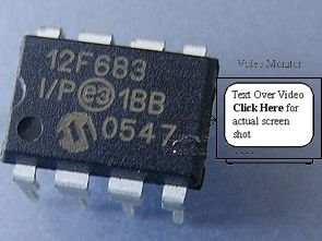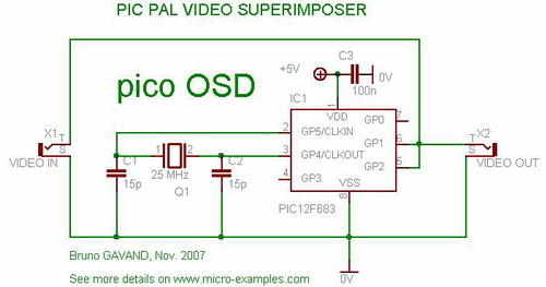
PAL video OSD circuit is made with pic12f683 and software is prepared with picc language, working frequency 25mhz circuit uses a lot of material (oscillator stage and supply filter capacitor) circuit diagram source C, hex codes are available.
The idea of this circuit is to push the limits of an 8-bit PIC to create an inexpensive video overlay: The MCU outputs the PAL sync in real time and inserts a line of text into the video. The PIC12 MCU is slightly overclocked: 25MHz instead of 20MHz max No jammer : output signal is directly added to input signal, not very clean but good for demo
PIC PAL video OSD
The PIC is overclocked with a 25 Mhz crystal but it should accept it with no problem. If you want not to overclock it, then use a 20 Mhz crystal and see C source code to know what adjustment to do. The result will be thiner pixel width.

The C source code contains the SETPIXEL(c) macro, not the Assembly. Video synchronization and production is done with the cut routine, the main loop only controls the shape and position of the text:
To overlay the text on a PAL video signal, we need to fine-tune the timing to get a stable picture. We have to deal with vertical sync, which tells us when a new frame starts, and horizontal sync, which tells us when a new line starts.
Usually, and external circuitry is used to extract both vertical and horizontal sync pulses from the PAL video signal, for example the LM1881 integrated circuit does this very well.
Since I wanted to have a very simple circuit, I had to find a way to get the PIC to do this job.
First, we need to know when a video line starts: we will use the PIC internal comparator module to do this. The internal voltage reference module will be programmed with a voltage cut level, then the comparator will trigger a cut if the input voltage is lower or higher than the clip level. This will be our horizontal sync splitter.
Second, we must know when a frame starts vertical sync: the PAL signal uses special sync pulses to announce a new frame. We have to detect a low-level pulse of 28 µs, there are five in vertical sync and nowhere else. The internal timer module of the PIC will be used to time the low level pulses.
Once this is done, we need to know what to superimpose on the video signal. A bitmap representation of the text to be displayed is resident in RAM from the 5×7 font table. At each new line break we check if we are in the display time window to add pixels.
To add a pixel to the video signal, we change the output pin from high Z state to output, then the output applies +Vcc or 0V to display a white or black pixel. The result is text overlaid on a transparent background.
Source: micro-examples.com PIC12F683 Video Text PAL – OSD schematic source code alternative link:
Şifre-Pass: 320volt.com
Publication date: 2008/08/10 Tags: microchip projects, microcontroller projects
PIC16F84 Ammeter Circuit 0-80A UGN3503
PIC16F84 Ammeter, ampere meter circuit pic16f84 microcontroller has been made with the current sensor is used for UGN3503 hall effect sensor output op amp with integrated lm358 strengthened pic16f84 RB0 pin connecting led display current information (lts542r) displays on the microcontroller, hall effect sensor with the current measuring is a good example
7-segment LEDS and bar graph display plus 2-digit display
5A step bar chart ± 0-30A indicator
2-digit display 1A resolution
Typical 80A maximum reading
Charge and discharge for dual display
Low light conditions automatic screen dimming