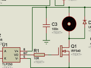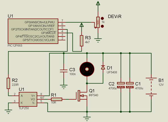
Hello Friends. I have done this summer, an engine control circuit I would like to share with you. While the maxima in the load circuit attracting a stream of about 10 to 12V DC vicinity of a fan I’ve done to the engine speed setting. Circuit works very well. I use my motor 12V at full load, while revenue was approximately 8.5-9 Amps current draw. I used the IRF540 mosfet circuit. This MOSFET 22 Amps if you can take while in full satisfaction. Because of the high current MOSFETs in the circuit are not overheated.
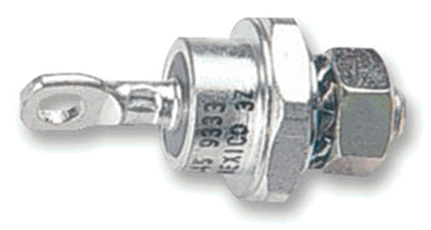
In addition, 12 ampere circuit at the input diode of the diode can withstand metal-sheathed hooked. There were a few for my hand until I thought I’d use them. I was put against the risk of reverse income. Exactly like the picture


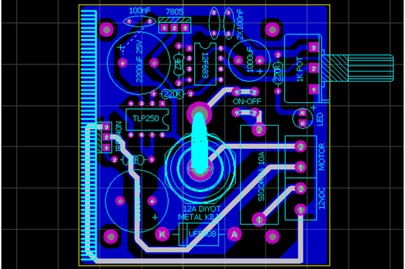
Proteus isis simulation of Motor control circuit, ares pcb and source code files:
FILE DOWNLOAD LINK LIST (in TXT format): LINKS-18104.zip
Publication date: 2011/12/12 Tags: microchip projects, microcontroller projects, motor control circuit, motor driver circuit, pwm circuits
Adjustable Current 6V 12V Battery Charger Circuit
I’m looking at a project for battery charging circuits, I found a very nice circuit applied a 6 volt 12 volt batterys worked the circuit for high-current battery is rechargeable, Kenwood. Charging circuit 2 protection, indicator when the battery voltage is set one over charge protection is active and the other is the deep discharge protection is very low-voltage battery is connected to the active (not just aimed at the protection of the property of the legend) I did not use the portion of the discharge. I fixed the various charging circuits, but there is no application, thanks to some detail so much a withhold help and answered my questions about disabled Kuhl