Pic with ASM programs may be useful tools for writers to asm “delay” delay time code to the given value (cycles) automatically calculates and displays based program does not require installation grew 320kb
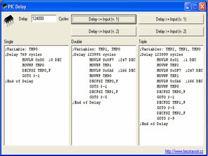
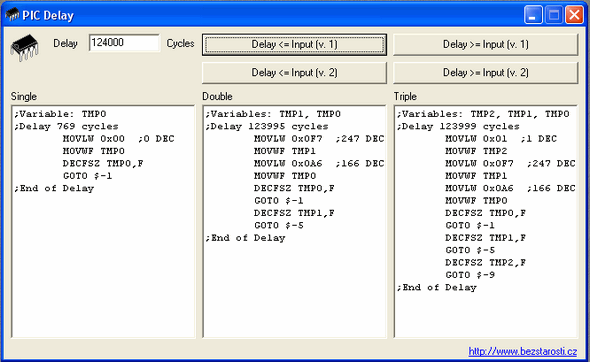
Delay PIC screenshot;

This program was born out of the need to write several complete wait cycles for the PIC, especially for applications where the execution time of the command is calculated and the time is required to complete either its cycles or to complete individual branches of the program.
Just extract the program from the zip file and run it. It is designed for Win32 (e.g. Win95/98). In the edit window after the word Delay, write how many cycles the resulting code should take. Then press the desired button, i.e. if you need to wait until the time you specify, press one of the Delay <= Enter buttons. If you do not like the result, you can try the second button. It is clear that it cannot always be produced exactly like this, so you can take a solution with a slightly shorter execution time and complete it by adding NOP commands to extend one cycle or GOTO $+1 to extend 2 cycles. If you prefer a longer execution time, press Delay >= Input. There are 3 solution windows. The first is for the single-cycle solution, the second is for the two-cycle solution and the third is for the three-cycle solution. The program will write to the windows the value closest to your input that can be solved in a predefined way in the program. For example, if you try to create a 500000 loop wait with Delay <= Input, it is clear that the single loop solution will have a significant deviation, because it will print the maximum possible value that can be achieved in this code, and if Delay >= Input requires a solution, then it will print in the corresponding window that it is not possible.
How can you put it in your code?
You copy the creations to your editor where you need them. In each window where the solution is located, the TMPx variables are noted, which must be defined in some universally applicable registers, how long the loop will take, and also so that you do not overwrite any registers you use in the program. I think this is clear.
What is the best way to write code?
Here I will describe the procedure, how I do it, that is, how I got used to it. I just write the program without thinking about what, where and how much time it will take, and I solve all the jumps to different branches in such a way that it is possible to write a code to call or wait for each branch in time, or if it is a short and clear structure, I do it immediately. Then I calculate how much time each branch takes and balance all the code branches so that it takes the same time everywhere. You can use this program to generate code for this, so when you realize you need to complete it, you enter that value for example 5000 cycles, press the button and get the generated code as an addition to your code.
A simple example.
We will want to make a program to flash an LED that should turn on and off exactly half a second later. In practice, we will use an internal 4MHz oscillator for the PIC, which means 1 instruction cycle per 1us for 2us jumps. Of course, better accuracy can be achieved by using a 4MHz crystal, but we will not deal with that now. So we will write the skeleton of the program and after setting up the PIC, it will include the main loop of the program where the LED will turn off, the LED will turn on, and the GOTO jump to turn the LED off.
Now we still need to fill in the times. So after the LED turns off, the LED should turn on for 500,000 cycles. It takes 1 cycle to fade out, so after it fades out we still need to wait 499999 cycles, so we create this pause and place it after the LED fades out. With the Delay <= Input (v.1) button it works just fine for us so we don't need to add anything else. Now we need to add the time after the LED turns on. It takes two cycles for the GOTO to turn off and one to turn off, so we add up to 499997 cycles. In the third window we can use the same button as before, so when the LED turns on and the program is complete and the timing is right we enter the code from the third window, so we have created a time base with a frequency of 1Hz and they change perfectly 1:1. For a better idea, I also add the program code to display it like this: onehz.asm . It is obvious to me that an experienced programmer would write in a shorter style for this task, but this should also be a clear example for beginners, so I preferred a completely explanatory example where there is no need for an overview of these things. Oscillators and pulse generators.
I think that every beginner understands from the example that it is possible to make an oscillator with a certain frequency from a single chip with this simple method, and if we take into account its price of around CZK 50 (in April 2002). The retail store for the PIC12C508A, including VAT, is certainly not bad financially, regardless of the fact that other functions, such as frequency switching, can be easily assigned to a specific pin, for example. If you use a crystal connection instead of a connection with an internal oscillator, it is possible to choose a frequency that suits the PIC's operation, and the timing will also be crystal-precise. So, in cases where a really precise frequency is required, the crystal or It is best to use a crystal oscillator. If you need to generate different waveforms (pulses) on a pin set as output according to the state of the input pins,
Waiting subroutines and program optimization.
If you are going to use the wait loop multiple times in the program, it is definitely better to write it as a subroutine and call it using CALL, in terms of the program memory space used. In this case, create 4 shorter loops than you need using the wait program, because calling CALL at the end of the program and returning RETURN takes exactly 4 extra loops. Another thing that you can sometimes see and that a beginner sometimes does not immediately think about is that when writing a subroutine, he does not have to call it from everywhere in the program, but can call it from somewhere in the middle. I will give an example.
CEKEJ9 GOTO $+1

NOP

CEKEJ6 GOTO $+1

RETURN
Here it is clear that CALL CEKEJ9 will do everything from CEKEJ9 to RETURN, and even with CALL and RETURN it will take 9 loops. GOTO $+1 is just a jump to the next line of the program, so it does essentially the same thing as NOP, but takes 2 cycles instead of one. Calling CALL CEKEJ6 is probably obvious, and it’s also obvious that it saves space compared to having each subroutine separately.
It’s also nice to have to wait 4 cycles to CALL RETURN a bit from any subroutine, so it’s just one more memory location for a 4-cycle-long pause. If the program is always going to produce some kind of waveform on the output based on just the pin drop, you don’t even have to think too much about how to do it economically, because if you can fit it into the PIC, no one will notice the difference between the program taking up, say, 50 bytes compared to the entire memory,
License.
If you leave the program unchanged, you can use it, spread it, put it on your website, and do whatever you want. No bounty can be claimed for this program, so it can only be distributed for free. You can use it completely free and commercially to create your applications without any restrictions.
Source: http://bezstarosti.cz
Şifre-Pass: 320volt.com
Published: 2011/05/17 Tags: electronics software tools
Edding PEN Draw PCB Printed Circuit Board
I used to print circuits directly plaque edinger with the stylus on the drawing would have made after the copy paper began using printed circuit copy of the Remove the paper plaque insert with pencil pushing copies passes over I print plaque after they were uttered edinger and goes through what I’ve been trying am I 🙂 hey go hey
This of introduction Ramada similar but slightly more practical as you can before the printed circuit on a paper transferred Want drawing you want from the printer after the paper copper plaque placed tape fixed with the hammer and the nail prints in the circuit hole (pad) segments is nailed after edinger the drawing is being made hole locations are announced for the paper looking a little easier to draw a different method