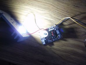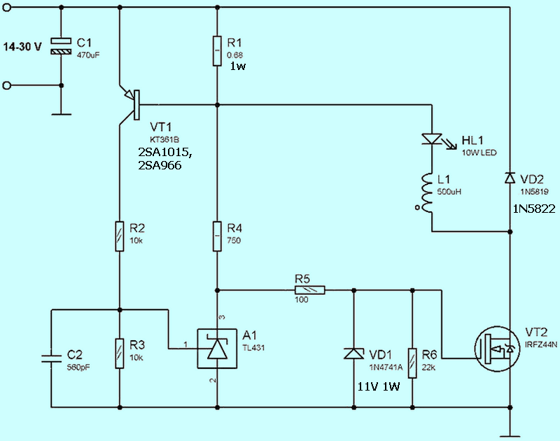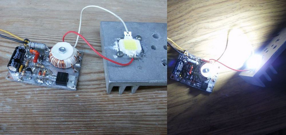
The 10W LED Driver driver circuit is designed to operate a 10 watt LED matrix (3×3, 10-12V) with current limitation. It works in the Step-Down system. The ring core used for the 500uh coil is approximately 80 turns of winding with 0.55 mm diameter wire taken from the filter located on the output stage of the computer power supply.
According to measurements of the 10W LED Driver, the efficiency is 90% at an input voltage of 13-20 V. The efficiency at a voltage of 30 Volts is about 83%. The LED current is quite stable for the entire input voltage range of 10-20 mA. between
When the input voltage drops below 13 Volts, the circuit starts to operate in linear mode, in addition, the brightness at the time of transition changes slightly and the efficiency does not noticeably decrease. As the input voltage rises to 1.5 – 2 V higher than the voltage on the LED, the device goes into switching stabilization mode continuously.
PCB dimensions can be used in the TO-220 package designed for the IRFZ Mosfet D2PAK package in 40mm x 60mm PCB design. The cooling of the Mosfet transistor is provided via the PCB. There are source PCB drawing and Proteus simulation file prepared with Sprint layout.
With the R1 Current limiting (0.68 ohm 1W) resistor, the current of the LED is about 800mA, where the measured voltage drop is 11.3 V, giving about 9 watts of power LED` 10% for longer life less than. The rated current of 980 mA in the datasheets of the 10W LEDs yields a voltage of about 11.5V on the LED and a power of almost 11.5 watts, significantly shortening the life of the LED.
10W 800mA LED Driver Circuit Diagram


PCB, Proteus simulation files of 10W LED Driver circuit 28230a.rar pass: 320volt.com
source: cxem.net/pitanie/5-324.php
Publication date: 2022/02/27 Tags: dc dc converter circuit, led projects, power electronic projects