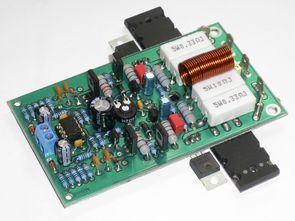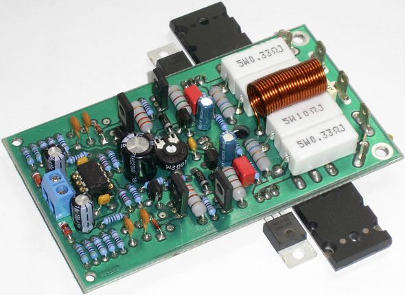
LYNX amp driver stage counted output transistors by increasing the number 500w, ….. 1000w amp circuits is done only on the drive slightest changes happening LYNX mini-project 2 power transistors used accordingly in the output power 100w noise THD rate is very low (0.005) PCB design has been excellent
NPN power transistors: 2SC5200 instead used MJL21194 PNP: 2SA1943 used instead MJL21193 working voltage +-40v

The basic design of the “Baby of Lynx” amplifier is suitable for less experienced builders due to its very high complexity, but is more aimed at more experienced builders. Among the main advantages of the amplifier, in addition to its lower requirements, are its relatively small dimensions, which makes it suitable for use in multi-channel systems. Also, in terms of price, this amplifier is not expensive to build.
Usually and today it is almost never the case that these characteristics go hand in hand with sound quality. The amplifier can really surprise you. Despite the low cost associated with its construction, the amplifier provides very low distortion and a high signal-to-noise ratio. Excellent sound parameters are achieved, among other things, by using excellent ON brand driver transistors and high-quality Toshiba brand terminal transistors, designed for direct applications in the field of audio amplifiers.
The sound parameters of the amplifier will satisfy even the most demanding listeners. The connection of the amplifier is very similar to the legendary studio amplifiers of well-known brands such as Phase Linear, SAE, GAS or Revox. The amplifier schematic is based on the link published by Danish designer Jan Dupot on his website as a non-commercial project for the general public under the name Lynx Power Amplifier v. 2.2.
I present to you my version of the amplifier called Baby of Lynx, which I spent a lot of time modifying and creating prototypes. And not only that, I believe that the amplifier will serve some designers for a long time and reliably, and they will definitely be very pleased with it. As for the choice of components, it is up to each reader to choose branded components and their quality or lower quality counterparts. However, I think that with widely available components it is possible to create a functional and reliable amplifier, the sound of which will sound very clean and undistorted even at higher volumes. At relatively low costs, it is possible to create a dynamic sounding amplifier that can also be used in studio conditions.
The well-known and respected Czech audio technology designer Mr. Pavel Dudek participated in the design of the original Lynx 3 amplifier [1]. The version presented here and edited by me won an award at the SVOČ (Student Scientific Professional Activity) competition in the “Electronics” section.
The measurement of quality parameters was carried out with the Audio Precision SYS 2722 measuring device. This sound analyzer allows measuring both analog signals in the acoustic frequency range and digital signals with a maximum sampling frequency of 192 kHz. According to the manufacturer’s website [3], the total harmonic distortion of the analog output of the generator is less than -115 dB at an output voltage of 2 V. The advantage of measuring with the help of this sound analyzer is not only high measurement accuracy, but also low complexity of the resulting measurement chain.
The unbalanced analog output of the SYS 2722 analyzer and the unbalanced analog input of the SYS 2722 analyzer were used to measure the amplifier sample. From the measured frequency characteristic of the functional sample of the amplifier, it is visible that the amplifier amplification is 28.355 dB. The resulting width of the transmitted bandwidth of the functional sample of the amplifier was also subtracted from the frequency characteristic, which is 180 kHz when the frequency characteristic changes by 3 dB. Such a bandwidth can be considered quite sufficient for an audio amplifier.
The power bandwidth of the amplifier was determined when the frequency response decreased by 0.05 dB to 20.5 kHz (20 Hz-20.5 kHz). The measured value of the power bandwidth is also completely satisfactory. The frequency characteristic of the measured sample of the amplifier can therefore be considered balanced over the entire acoustic frequency band. Then, measurements of the dependence of the total harmonic distortion factor THD on the amplifier excitation (output power) for various frequencies of the amplified signal were made.
Electronic manufacturers usually list the total harmonic distortion factor for their products mainly for an input signal frequency of 1 kHz. The total harmonic distortion factor of the amplifier can therefore be determined exactly from the resulting characteristic measured at a frequency of 1 kHz. The resulting THD value is approximately 0.004%. A typical THD value is below 0.1%.
The resulting value of the total THD distortion factor therefore fully meets the given requirements. For a working sample of the amplifier, the power difference between the useful signal and the noise was measured. The measurement was carried out under two conditions. In the first measurement, the signal-to-noise ratio was measured without including the weighting filter in the transmission path. The resulting signal-to-noise ratio was 89 dB. During the next measurement, an A-type weighting filter was included in the transmission path.
This filter takes into account the frequency dependence of human hearing, when disturbing noise is less perceived at the edges of the frequency band (20 Hz-20 kHz). This filter was included
Şifre-Pass: 320volt.com
Publication date: 2011/06/10 Tags: audio amplifier circuits, transistor amplifier
Tube Tone Control Circuit 1SH29B
c 4 1SH29B lamp used bass, treble, gain and volume controls able supply 200V 15mA and 5v 200mA DC separate circuit diagram in key areas of current and voltage data indicated pcb print circuit drawing layout quite been good over-current for the author 10w transformer He trained with the circuit. 1SH29B sprint circuit’s layout has been prepared by the PCB on file.