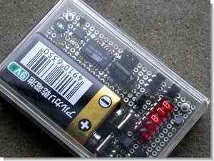
The lux meter circuit displays the lux value on the LED display built on the Atmel Attiny26-16 microcontroller. The LEDs are driven by 2SK1061 MOSFETs. An interesting application. All source files (PCB, schematic, code) are shared and the calibration information of the circuit is also given.
Lux meter circuit diagram
Lux Meter is often used to measure illumination. Illumination is how the level of luminous flux falls on a surface area. Luminous flux is the visible component defined as the radiant flux (light power) divided by the relative sensitivity of the human eye over the visible spectrum. This means that Lux corresponds to the level of light perceived by the human eye.
However, there is a difference between the spectrum response of ordinary silicon photodiode and the spectrum response of the human eye, it cannot be used for lux meter. Some photodiodes for the illumination sensor have a color balancing filter in the window to correct the spectrum response.
Equipment
When used in short mode, the photodiode delivers a luminous current that is well proportional to the input light power. In this lux meter, the output current is converted to voltage by the IV converter, captured by the microcontroller and displayed in lux. The ppamp U1 in the Circuit Diagram acts as an IV conversion circuit and the conversion rate is 50mV/µA according to the feedback register R5. Capacitor C5 is for obtaining rectification, it cancels the Ct of the photo diode (about 200 pF). In this case, larger capacitance instead of 220 pF might be good since there is no need for high frequency signal.
The lux meter operates on a 9V battery. To minimize battery space, the battery snap is replaced by two springs made of nickel-plated copper-phosphorus alloy. But it is not an anti-reverse input structure, no protection circuit is needed. Q1 is a reverse input protector with no voltage loss like a series diode. It is a main switch that forms a power holding circuit with Q2, Q3 and Q4.
U4 is a 7-segment LED display from HP. It is housed in a 14-pin DIP package. It is useful for useful equipment, but it is not suitable for battery operation as it consumes little power.
Lux Meter Software
The main function of the firmware is simply to capture the sensor output with the AD converter and display it on the LED display. The AVR’s built-in AD converter has 10-bit resolution but is a bit inadequate for an industrial measurement system. The AD converter unit has a gain amplifier that can be placed between the multiplexer and the AD converter. This allows improving resolution by automatically varying the input gain. To implement this function, capture the input at a gain of 20, if overflow occurs, capture it again at a gain of 1. As a result, it can improve resolution at small input resolution, which reduces the relative resolution. Maximum light input approx. 30000 lux due to 0 to 2.56 V AD input boost.
The result from the AD converter is multiplied by a calibration value to the LED display in lux. In case of low battery, the LED will blink.
The power switch is held by the microcontroller to control the power itself. This is useful to prevent forgetting to turn off the power. This lux meter turns off the power in 60 seconds.
Lux Meter Calibration
In most cases no reference light source will be available. To calibrate the lux meter we need to rely solely on the datasheet. According to the S1087 datasheet, the short current is Isc = 0.16µA/100lux. At 1250 lux it is 2µA. When -100 mV is applied to the test pin (TP1), it is equivalent to 1250 lux in the photo diode and the IV converter will output 100 mV.
To perform the calibration, connect the ISP pins with a few kΩ resistor, turn on the power and it will be calibrated according to the reference input. Low range is calibrated when SCK-GND and -100 mV at TP1, High range is calibrated when MOSI-GND and -1 V at TP1. Of course the photodiode must be masked during calibration, otherwise the result will be invalid. When the lux meter is placed in any transparent casing, including the light sensor, additional calibration is required to account for attenuation due to the casing. Closed lid and when lux drops 10%, recalibrate with 10% reduced voltages.
Calibration is easy if any reference lux meter is available, find the 1250 and 12500 lux locations and calibrate at those locations.
source elm-chan.org/works/lux/report.html Lux meter circuit files alternative link:
Şifre-Pass: 320volt.com
Publication date: 2010/03/07 Tags: avr project, microcontroller projects

JAL Examples Circuits, of JAL Library
Jal `e Grabbed a short time ago seemed so easy to me 🙂 I did not even subject to an application by the way, I went hunting for information documents I’ve created a solid jal archive. Jalan people who want to program the pic can be a good source for at least i think that time is not wasted
In the meantime, my experiences I direct that we know (Serkan crescent JAL WITH PIC Programming) Jane `s support negligibly small, many people JALV2 using basically the same count, but there are differences for individuals interested in the latest version would suggest the files in the program files have the program after installing the file lib folder in the C: \ jalpack take into