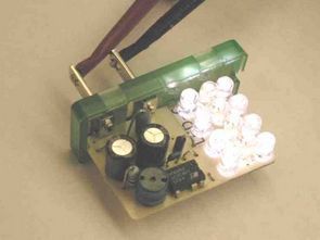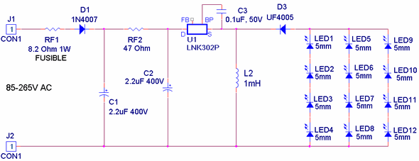
Non-Isolated Converter circuit mains voltage half wave input voltage available 85v rectification … 265v ac especially suitable for white LEDs run already in practice 12 white led on led run of the circuit performance focused plowed.
The biggest advantage of insulation of the circuit (lnk302p) as shown in the diagram, the lack of mains voltage dez with direct connected transformer is obsolete, but the resistors, capacitors made by using a healthy circuit than 220v circuits regulate

LNK302P Features
• Low component count (only 9 components required)
• Low Cost, Lightweight, Compact Solution
• No Opto-Coupler Required
• Open Loop Operation
• High Efficiency (~70%)
• Meets EN55022 B EMI Limits with >8dB margin
Circuit Description
This is a very simple circuit that requires as few as 9 components. An additional inputb diode can be placed on the return leg for EMI and surge withstand capability. The LNK302P is used in open loop mode for this circuit. This particular device does not have an auto-restart feature in the LinkSwitch-TN family and therefore when the feedback pin is left open, the MOSFET current limit (or duty cycle limit) is reached.
This LED driver operates at 66 kHz and energy is provided for each cycle of the LED. Since the circuit operates in discontinuous mode, there is a fixed amount of energy stored in L2 for each cycle, then transferred completely to the load (i.e. the LEDs). The current in this LED is a triangular waveform determined by the peak constant and the well-controlled current limit of the LNK302. The load current is therefore independent of the line voltage. In this way, the need for an output filter capacitor is completely eliminated.
Input EMI Filtering: Resistors RF1, RF2 and capacitors C1 and C2 form the EMI filter. C1 C2 and RF2 are connected to form a low-cost resistive π filter and provide excellent differential mode filtering and also serve as a stable DC bus voltage. Resistor RF1 is a fusible flame-resistant type, while RF2 can only be flame-resistant.
Output Rectification
Since this circuit operates in strictly discontinuous conduction mode (DCM), a 75 nS recovery time UF4005 diode is used for output rectification. The buck boost topology also provides the benefits of isolating the output from the input in the event of a switch failure
Şifre-Pass: 320volt.com
Published: 2011/03/19 Tags: dc dc converter circuit, power electronic projects
DC-DC Converter Circuit 3.3V 2A DPA423G DPA-Switch
Custom applications will work a 3.3 volt output voltage DC to DC converter circuit input high (36-volt to 72 volts dc) is the biggest advantage of the converter circuit integration with the production of the DPA-Switch DPA423G circuit with very little material based on. DC DC converter circuit is all about details of materials transformer information etc..
With the introduction of the full load of the circuit below 48 volt the heat has been a good performance measurement information