
The laser used for the transmission angle of the mirror should be set well above should be fixed and is 30cm from the ground. Mirrors, Laser, Ldr should be fixed and should sway camouflage Mirrors whether cables will yield more if stored.
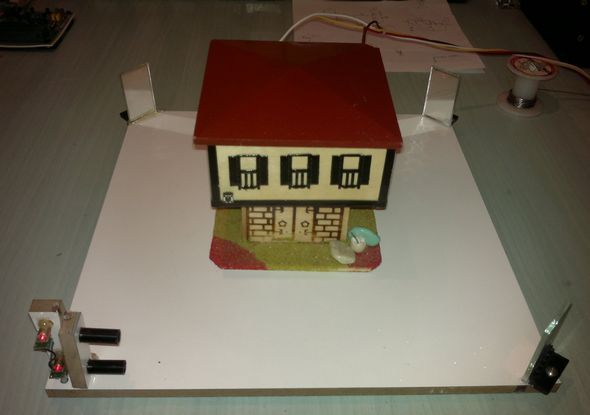
NOTE: 1 (when pressing the RESET button to silence the siren must have light on LDR s)
2nd half while adjusting the angles of the mirrors with LED 1 and LED 2 can be benefited from. )
Our environment is used as the light source laser light source as is known, they operate at low voltage of 12v circuits we feed our 9 to the end of the laser must be connected to the 220 ohm 1W resistor. That will reduce the resistance heating of 1W.
Laser Barrier Schematic PCB
Material List
| conductors | Resist | Others |
| BC327 – 2 Pieces BC547 – 2 Pieces BC338 – 1 Piece BT169T – 1 Piece |
LDR 2 – Quantity 100ohm 1 – Quantity 220ohm 1W – 1 piece 390ohm – 2 Pieces 1K 2 – Quantity 4.7K – 2 Pieces 22K – 2 Pieces 100K – 1 Piece 240K – 2 Pieces |
Kırmızı LED – 2 Pieces IşıLight Sourceğı As Laser – 2 Pieces Mirror 5×3 cm – 3 Pieces &Cedil;workışworking Floor 30X30 cm – 3 Pieces 5X3 cm Copper Plaque 1 Piece Conductive cable as needed Silicone or similar glueıştırıcı Between 9 and 12v DCı power sourceğı |
Published: 2008/12/24 Tags: analog circuits projects, simple circuit projects

8051 Programmable Power Supply
Circuit Operation: Circuit diagram appears in the 0-5 the entered value from the keypad circuit, which is connected to port P1 applied to the integrated DAC 0808 DAC output is obtained from the analog voltage. P0 port is connected to the 7-segment display of the absolute value of the voltage, which is connected to port P2 indicator shows the decimal value of the voltage. On the keypad “*” key to delete the entered value, “#” key, the entered value is used to convert the analog voltage. Output of 0-5 V 0.1 V-0, 2Volt precision analog voltage is obtained.