Line follower robots are still popular. Finally, someone did something different on the line follower robot and shared the source code and the project.
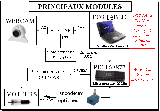
The robot has a program written in CPP for the camera (webcam) part, the microcontroller used in the control circuit is pic16f877 software, all source codes prepared with PIC-C are protel PCB files Communication with the PC is provided with MAX232 and the motor driver used in the circuit is L298
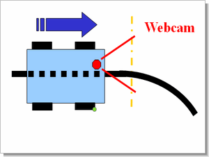
Basically, the analysis is done on the image line by line. Finds the minimum and maximum values in black and white for each line. It then repeats a pass and finds “dark regions” (not shown here), which are regions with a certain percentage of black with a small hysteresis.
From these dark areas, it draws a “main” continuous dark area for each line. How does he find it? Well, first it assumes it’s in the middle (in the 1st image), then it uses the last position (previous line or previous image for line 1). The main dark region below is closest to the previous one (I adjusted the coefficients), knowing that the thickness of the region also plays a bit.
The middle of this main dark area is marked by the red dots visible in the picture. Thus is the line where he makes enslavement! Each line of the image has a red dot.
Otherwise, the horizontal line is a line that shows where it no longer considers a line to follow. How does it work ? It’s actually very simple, I’m looking for a jump of more than “X” pixels between 2 red dots on consecutive lines. If they are placed in a line, they will not be too far from each other. On the other hand, if it’s no longer a line, the dots are somehow placed anywhere and jumps happen detecting these jumps, knowing that there is no longer a line to follow (of course that doesn’t work 100%, but it’s accurate enough for our purposes).
The robot will keep an eye on a few lines of the image (it’s fair to say). In particular, if the horizontal line begins to descend too much, the robot automatically slows down (to make better cornering). And if the line is really low, the opponent will slow down sharply (if he catches up with him, of course) to avoid hitting the robot.
Line following robot

source : fribotte.free.fr PIC16F877 Line following robots Project alternative link
Şifre-Pass: 320volt.com
Publication date: 2009/10/21 Tags: microchip projects, microcontroller projects, pic16f877 projects
Negative Delta-V Battery Charging Circuit LCD Display PIC16F876
Previously published as automatic charging system is the advanced version of my project I designed a new system using the 16F876. Without much change in the electronic portion of the system say the changes made in the program. I have done previous system 16C711 (once programmable) was working with the pic. Also cut off the end of the charging process is that the battery is full to understand that I was used Negative Delta-V system.
For those who are negative delta-V’s once again let me explain what I mean. quite voltage charging NiCd and NiMH batteries are rising. Following the rise of the voltage of the battery is cut off and stuffed after this stage of 10-20 mV per battery is a voltage drop. If you need to give examples of when one NiCd battery discharged voltage of around 0.8 V is about.