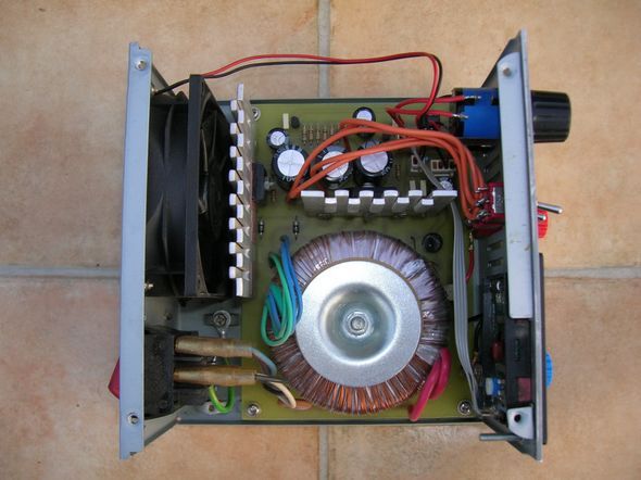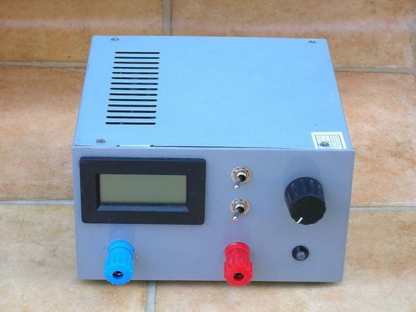
The laboratory power supply circuit is similar to the classical transistor power supplies, the mosfet irfp150 is used as a power transistor, the author has placed the circuit in the pc power supply box, added a volt meter module, and a toroid transformer is used in the circuit, which can be used in normal sheet transformers.
The basic device in an electronics workshop is a stabilized power supply. After 8 years of using a simple 2-volt power supply (12V and 5V), I decided it was time to replace it. During construction, I was guided by the principle: “the simpler the better”, because the power supply is constantly used for work, not for repair.
– power supply 230V AC (tolerance +10% -20%),
– linear stabilization,
– output voltage freely adjustable 2.5 – 27.5 V (linear regulation, stabilization accuracy 1%),
– Current regulation in 2 ranges, 0.2A and 2A (accuracy 10%),
– signaling of operation in “current mode”,
– digital voltmeter,
– the possibility of continuous operation even in the worst conditions (2.5V 2A),
– switched transformer stage to reduce power losses at low voltages,
– two-pole main switch,
– chassis ground connected only to the reset pin and isolated from any potential of the system,
– fixed desktop enclosure (metal).
Laboratory Power Supply Project (atx casing)


Mains voltage goes to the primary winding of the main transformer via a bipolar switch (100% disconnection accuracy, no hum from the switched off power supply) and a polymer fuse. A 50W toroidal transformer (high efficiency) was used. The power balance indicates that the maximum power consumed is about 70 W, but forced cooling provides more sustained power consumption.
The 2x15V split secondary winding supplies a 1000u / 63V battery with 3 capacitors via a rectifier bridge (6A max – in the heat sink from the PC power supply).
Using 3 capacitors for higher voltage significantly increases their life – current is distributed across the 3 capacitors and higher voltage capacitors have lower ESR – internal resistance, hence they dissipate less heat. The front switch changes the rectifier configuration from half-wave (low voltage) to bridge (high voltage) – this allows you to reduce power losses when working with low (up to 14V) voltages. Both sections of this switch are bridged for longer life. The execution element is the MOSFET transistor IRFP150 (100V, 40A). The use of such a large transistor was related to the desire to provide the highest possible durability and reliability, as well as the low thermal resistance of the TO26… housing.
Voltage stabilization is carried out using a fine-tunable zener diode D3 (LM431). The condition for its correct operation is to provide it with a current of 1 – 100 mA while maintaining maximum dissipation power. An additional rectifier on diodes D1 and D2 (and two diodes from the MO1 bridge) provides a high enough voltage (regardless of the position of the tap switch) to power diode D3.
The control input of the D3 diode is connected to the output (as close as possible to the output terminals) via an adjustable voltage divider – the upper branch has a precision potentiometer that provides precise linear regulation (2.5V/10 to be exact). rotary). It should be noted that the executive transistor operates in a common drain (follower) system and needs a gate voltage about 4V higher than the source voltage to fully turn on.
At the source of this transistor there are switched resistors used to regulate the overload current (current operation). If the drop on them exceeds the turn-on voltage of transistor T2, it will limit the control of the transistor, thereby limiting (stabilizing) the output current. As you can see, the accuracy of this arrangement is highly dependent on the switching voltage of the bipolar transistor (about 0.65V) and is not very accurate (depending on temperature, among others).
In the higher current range (R5, R6, R7 attached) the output current flows through the switch and the voltage drop across it affects the stabilization of the current so both sections are connected in parallel. However, in applications where the system is designed (battery charge, protection at system startup), control sensitivity is not a problem. Simplicity and thus operational reliability is also the focus here. The output has a reverse-opened diode D7 (3A), which protects against the introduction of an external voltage with a reverse polarity to the external power supply.
In the transformer core there are 3 windings (15V), which are used through a rectifier, filter and 12V stabilizer to power the fan, a voltmeter (which must be galvanically separated from the power supply measurement circuit), and diodes that indicate that the power supply is working. (voltage/current). To control the status diode, an optocoupler included in the current limiting circuit was indirectly used – burning its diode changes the color of the status diode from green (voltage) to red (current).
It was all enclosed in an enclosure after a PC power supply, I just made the headlight myself. attached drawing. The power supply socket, fan and heat sinks were used for the construction.
The proposed build is the result of experience with complex builds suggested in the literature (mostly with bugs related to the current stabilization cycle, which wasn’t particularly for me).
230V AC power supply (tolerance 10% -20%),Stabilizing linear
Output voltage regulated smoothly 2.5 – 27.5 V (linear regulation, the accuracy of stability 1%)
The regulation of electricity in 2 ranges 0.2 A and 2A (an accuracy of 10%)
Signaling work in the “current mode”,
Work continued even in the worst conditions (2.5 V 2A),
Switched off the transformer for power losses at low voltages,
Bipolar circuit breaker network
The combined weight of the casing only with mechanism and isolated from any system capabilities,
Stable housing Desk (metal).
Source: sq2ahr.sp-qrp.pl 2.5v – 27.5v 2Amp Laboratory Power Supply Circuit PCB schematic alternative link:
Şifre-Pass: 320volt.com
Publication date: 2008/10/23 Tags: power electronic projects, power supply circuit, power supply project
Digital Clock with Lemon Run
Let’s start from the very beginning. In 1,790 years Alexander Volta built the first cell plating, which has been called stosem Volt. It consisted of coins made of two different metals interleaved alternately electrolyte paper pad (in this case, salt water). As a reminder: cell plating is a chemical link, which are a source of electricity by chemical reactions that take place between the electrode and electrolyte. Two electrodes submerged in elektrolicie (half cells) make up the cell plating. The difference between electrode potentials elektromotoryczna the force of the cell (SEM).