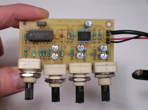
ICL8038 20Hz 20kHz audio signal generator circuit can be useful in testing various circuits, especially amplifier circuits. The heart of the circuit is ICL8038 (Precision Waveform Generator/Voltage Controlled Oscillator). Frequency adjustments are made with 100k potencies on the circuit. The working voltage is 12 volt dc.
Three small, simple sound generators that produce a rectangular, triangular, and sine wave on three separate outputs or a single output (mixed signals) waveform selectable via a small three-position switch or a unique small output mixer.
These assemblies are based on the use of a special integrated circuit called ICL8038 (Intersil or Harris), also available under the reference XR8038 (Exar). This circuit includes almost everything needed to make a small LF generator with modest performance and requires very few additional components.
– Diagram 002a : range 700 Hz to 18 KHz in a single range, one waveform at a time (mechanical selection)
– Diagram 002b : 20 Hz – 20 KHz range in three ranges, one waveform at a time (mechanical selection)
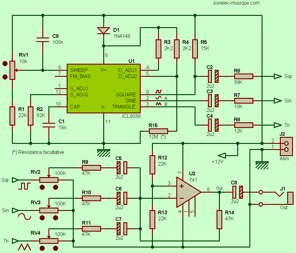
– Diagram 002c: 20 Hz – 20 KHz range in one range, mixable waveforms (integrated audio mixer)
Settings that allow fine tuning of the output signal (distortion reduction and symmetry adjustment) have been removed, but the circuit remains functional and adequate for its assigned role. Of course the frequency setting is preserved, it is RV1. High value resistor R15 is optional, it makes it possible to slightly reduce frequency variations in the duty cycle. Three potentiometers RV2, RV3 and RV4 are used to mix the three output signals.
The value of resistor R6 is higher than R7 and R8, providing greater attenuation for the square signal at startup than the other two (the amplitude is almost equal to the value of the power supply voltage). So there is at the level of the settings, a good balance of levels between the three types of signals. The summation is provided by the summation resistors R9, R10 and R11, the summation point of which is somewhat hidden by junction capacitors C5 to C7, leading to the inverting input of U2, a common AOP that can be replaced by any other.

Since no gain is required here (resistance is equal to R14 pickup resistors), the bandwidth exceeds 20 KHz and is therefore more than sufficient. Those who find this too “noisy” need not worry, the amplitude of the LF signals it processes here makes you forget about the little background noise. Is the rise time too long? There’s nothing stopping you from trying the OPA134 or the more modest NE5534…
The summation is provided by the summation resistors R9, R10 and R11, the summation point of which is somewhat hidden by junction capacitors C5 to C7, leading to the inverting input of U2, a common AOP that can be replaced by any other. Since no gain is required here (resistance is equal to R14 pickup resistors), the bandwidth exceeds 20 KHz and is therefore more than sufficient.
Those who find this too “noisy” need not worry, the amplitude of the LF signals it processes here makes you forget about the little background noise. Is the rise time too long? Nothing is stopping you from trying the OPA134 or a more modest NE5534… The pickup is the pickup point, somewhat hidden by junction capacitors C5 to C7, leading to the inverting input of U2, a common AOP that can be replaced by any other pickup resistors R9, R10 and R11 is provided. Since no gain is required here (resistance is equal to pickup resistors R14), the bandwidth exceeds 20 KHz and is therefore more than sufficient.
Those who find this too “noisy” need not worry, the amplitude of the LF signals it processes here makes you forget about the little background noise. Is the rise time too long? There’s nothing to stop you trying the OPA134 or a more modest NE5534… U2’s inverted input is a common AOP that can be replaced with any other. Since no gain is required here (resistance is equal to pickup resistors R14), the bandwidth exceeds 20 KHz and is therefore more than sufficient. Those who find this too “noisy” need not worry, the amplitude of the LF signals it processes here makes you forget about the little background noise.
Is the rise time too long? There’s nothing to stop you trying the OPA134 or a more modest NE5534… U2’s inverted input is a common AOP that can be replaced with any other. Since no gain is required here (resistance is equal to pickup resistors R14), the bandwidth exceeds 20 KHz and is therefore more than sufficient. Those who find this too “noisy” need not worry, the amplitude of the LF signals it processes here makes you forget about the little background noise. Is the rise time too long? There’s nothing to stop you trying the OPA134 or a more modest NE5534… no need to worry, the amplitude of the LF signals it handles here makes you forget about the little background noise.
Is the rise time too long? There’s nothing stopping you from trying OPA134 or a more modest NE5534… no worries There’s no need for a track, the amplitude of the LF signals it processes here makes you forget about the little background noise. Is the rise time too long? There’s nothing stopping you from trying the OPA134 or the more modest NE5534…
Source: sonelec-musique.com
20Hz to 20kHz Signal Generator Alternative link:
Şifre-Pass: 320volt.com
Publication date: 2010/05/16 Tags: audio control circuits
Transformerless Power Supply Calculator Program 220V MOSFET Stabilizer
Mains voltage to reduce the general sheet metal transformer used an electronic circuits and mains voltage we reduce the over-current uninteresting circuit to operate the ideal usually 220 volts ac voltage to one end of a series capacitor connected diode bridge resistor, the zener with the desired low voltage is obtained, but as I said, the power is very low.
Calculation program also facilitates the work of the calculating part of the computation is the circuit for MOSFET is alınabiliry higher power MOSFETS can be said that the regulator.
MOSFET Transformerless Power Supply