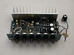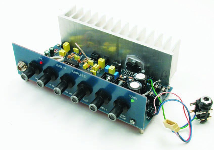
DMOs TDA7294 integrated amplifier guitar amp used for a variety of powerful sound, the tone control circuit TL071, TL072, TL074 op-amp ICs used
Voice in the introduction of control quite well GAIN, HI-MID, LOW-MID-BASS, TREBLE, VOLUME settings are all enabled electronic kompadent commercially available but quality potency little hard to find 4-ohm speakers and 2 x 12 volt supply voltage and 70watt power gives for 8 ohm speakers you can get 2 × 20 volt transformer power supply circuit using a full bridge diode used in place of 6 amps to me seemed a bit weak, I suggest using the bridge-diode
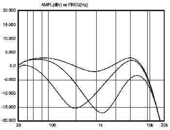
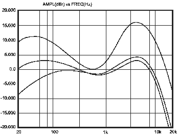
Four-point, independent tone control, adjustable signal limiter, overload signaling – LED diode, separate gain and master level control, two sockets for connecting devices producing special effects


The parts list for guitar amp
Resistors
R1, R6, R11, R32, R33, R35, R36,
R42 … R46, R48, R49, R59: 10 k
R2, R34: 470 k
R3, R54: 1.5 k
R4, R9, R30, R31: 3,3 k
R5, R12, R15, R18, R21, R24, R25,
R29, R38 … R41: 4.7 k
R7, R51, R67, R68: 2.2k
R8, R13, R19, R28, R37, R53, R56,
R58: 22 k
R10: 47 k
R14, R20, R27, R47, R55: 1 k
R16, R17, R22, R23, R52: 220 k
R26: 15 k
R50: 100 k
R57: 680
R60: 3 k
R61, R62: 270
R63, R64: 100
R65: 20 k
R66: 30 k
Capacitors
C1, C8, C18: 220 pF
C2, C3, C13: 22 nF
C4, C12, C17, C28, C29: 1 μf
C5: 68 pF
C6: 10 nF
C7: 68 nF
C9, C10, C11, C14, C21: 4.7 nF
C15: 150 nF
C16, C22: 2.2 nF
C19: 33 nF
C20, C23, C27: 680 pF
C24 2.7 nF
C25 1.5 nF
C26 3.3 nF
C30: 220 nF
C31: 10 μf/63v
C32: 470 nF
C33, C46: 22 μf/25v
C34, C38: 100 nF
C35 … C37, C39: 10 μf/25v
C40, C41: 2200 μf/25v
C42, C43: 100 μf/25v
C44, C45: 47 μf/25v
Integrated and Diodes
U1: TL071
U2, U3: TL074
U4: TL072
U5: TDA7294
U6: LM317T
U7: LM337T
Q1: BC547
D1, D2, D7, D8: C33
D3 … D6, D9: 1N4148
M1: BRIDGE Diode
DL1: LED CON2
DL2: GREEN LED
Other elements
P1: 47 k potentiometer
P2 … P4: potentiometer POT2
P5: 22 k potentiometer
P6: 2 × 10 k potentiometer
COOLING 180 x 50 mm
TRANSFORMERS 2 × 20 V 60W
guitar amp circuit diagram pcb files
Şifre-Pass: 320volt.com
Publication date: 2008/01/13 Tags: audio amplifier circuits, ic amplifier, tda7294 amplifier circuit
LM3886 Amplifier Project Tone Controlled
Beautiful, high quality Amplifier circuit. National Company of Used ruin his LM3876 Integrated with a few changes on the PCB LM2876, LM3886 Integrated NE5534 Used for Usable Tone Control Bass, Treble, Balance, Volume Controls have
Tone Control Features
20 Hz at 20 kHz.
+15 V, -15 V
2 x 13 mA.
(-0.2 DB):
0.01%.
92 dB.
DMOs TDA7294 integrierten Verstärker Gitarrenverstärker für eine Vielzahl von kraftvollen Sound verwendet, die Tonregelkreis TL071, TL072, TL074 Operationsverstärker-ICs verwendet
Stimme in der Einführung der Steuerung ganz gut GAIN, HI-MID, LOW-MID-BASS, Höhen, Lautstärke-Einstellungen sind alle aktiviert elektronische kompadent im Handel erhältlich, aber Qualität Potenz kaum zu finden 4-Ohm-Lautsprecher und 2 x 12 Volt Versorgungsspannung und 70 Watt Leistung ergeben für 8 Ohm Lautsprecher 2 × 20 Volt Trafostromversorgungsschaltung mit einer Vollbrückendiode, die anstelle von 6 Ampere verwendet wird. Mir schien es ein bisschen schwach, ich schlage vor, die Brückendiode zu verwenden
Hello, i’d like to know what’s the value of the P2, P3 & P4 Potentiometers are as long as the types of all potentiometers (linear or log taper). Love the project and thanks in advance!
Hello, P2, P3, P4 Potentiometers 22K
please kindly give us ” HIGH QUALITY GUITAR AMPLIFIER CIRCUIT TDA7294″ pcb dimention in centi meter or inch so that we making perfect size amplifier i hope quickly reply this comment thank you.
PCB dimensions of 188 X 76mm
I can use 20-0-20v 5 ampere transformer in this project.
Yes you can use 20-0-20v 5 amp. transformer.
i don’t understand potetiometer P6:2×10k and transformer 2×20v value so describe this and again thank you very much for this beautifull amplifier project.
2X10K: 10K Stereo potentiometer
Yes the transformer must have 2×20 vac output
Doesn’t work well with 2x12vac
Where can I get the whole kit
no sale, do it yourself DIY
What are the JP1, JP2 and JP3 connectors called SND, RTN and SYM respectively for?
Thank you for your answer.
Hi,
Before the signal is fed to its input, it is available in the sockets for connecting external devices. The signal in the JP1 socket is always present and can be used to make recordings on a tape recorder.
Devices that give additional effects while playing the guitar can be connected to the JP2 socket. If they are not connected, then contacts 1 and 2 of this socket should be short-circuited with each other.
On the other hand, in the JP3 socket there is a symmetrical output signal with an amplitude of about 1 V. It can be used for monitoring or to control an additional power amplifier.
Hello , i cant find TDA7294 , but i found TDA7293
I checked both data sheets and the only difference is in their voltage range.
Can i use TDA7293 instead of TDA7294 in this circuit that you gave us?
Thanks a lot 🙏🏻
Hello,
You can use TDA7293
hey, what is the type of the bridge rectifier?