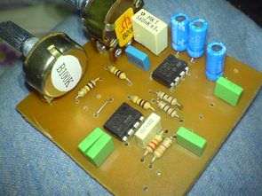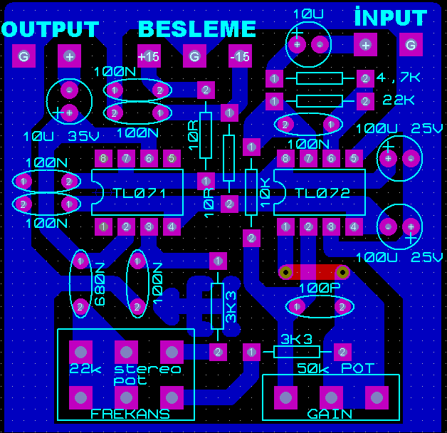
The adjustable frequency Bass Crossover circuit is based on two opamps (tl071 tl072) integrated circuits, the operating voltage is symmetrical +15v -15v, there are two pots for gain and frequency settings, the frequency range is 10…60hz.
Since the circuit consumes low power, it can be operated with zener regulated or 78L15, 79L15 regulated power supply circuits.
The adjustable Bass filter circuit only has a PCB drawing and layout plan, there is no circuit diagram

aothor: tamircihasan Adjustable Subwoofer Crossover circuit pcb files :
Frequency Adjustable Bass Crossover Circuit
Şifre-Pass: 320volt.com
Publication date: 2010/07/10 Tags: audio control circuits
60 Column Dotmatrix Scrolling LED Sign Circuit PIC18F452
The software installed on the marquee circuit PIC18F452 microcontrollers with PicBasic pro isis proteus simulation prepared and drive times ares pcb board pcb files have led matrix.