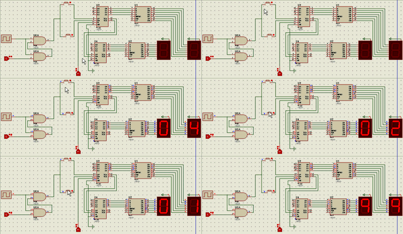
Billiards Counter Circuit Even if a counter circuit project is not implemented with the application circuit and detailed information, the information is very valuable. Thanks to the contributors
BILLIARD COUNTER In billiard halls, pool players use counters to write down the numbers they receive. The old-style counters were mechanical counters with a hand-turned cardboard display. Today, electronic counters have replaced them. TTL ICs are used in the electronic billiard counter circuit. The circuit is designed as two digits. If desired, the number of digits can be increased to 3 or 4. Since forward/back counters (74192) are used as counters, missing or overwritten numbers can be corrected immediately. 7447 was used as decoder.
ELEMENTS USED IN THE CIRCUIT
74192(PRESETTABLE SYNCHRONOUS BCD DECADE UP/DOWN COUNTER): 74192 IC is a presettable synchronous BCD up/down counter IC;
• IC pins 15,1,10,9 are respectively D0,D1,D2,D3 data inputs.
• IC pins 3,2,6,7 are respectively flip-flop outputs Q0,Q1,Q2,Q3.
• Pin 4 is the clock input to be used in case of DN count down.
• Pin 5 is the clock input to be used in the UP counting condition.
• 8 pin GND ground(ground),0V.
• Pin 11 PL asynchronous parallel loading, active Low=0, passive HIGH=1
• The asynchronous master reset input shown as MR 14 should be HIGH in active state and Low=0 in passive state.
• TCU pin 12 disrupts the fixed logic 1 status while ringing from 0,1,…,8,9 to 0 during counting up and becomes logic 0 for half of the 1 period. As soon as the number 0000 is reached, it switches back to the logic 1 state.
• TCD pin 13 disrupts the state of logic 1 during ½ T during counting down, from 9.8,…,1.0 to 9 (the moment of switching from 0000 to 1011) and becomes logic 0. This state ends as soon as 1001 is passed, and logic 1 is switched, and logic 1 is kept constant from 0 to 9 transition time.
• Pin 16 VCC positive source voltage.
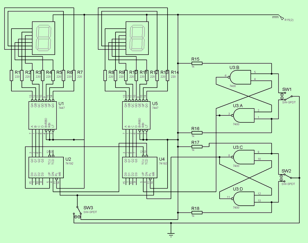
0-99 Counter Circuit Diagram

Two 74192 ICs are used in the circuit and these ICs act as up/down counters. D0,D1,D2,D3 data inputs are unimportant since PL (load) is in the passive state (load=1). By connecting a switch to the MR asynchronous main reset inputs no. 14 of the integrateds, they are enabled to be turned into active or passive position.
7447 (BCD/7 SEGMENT DECODER):
The 7447 integrated circuit is a BCD / 7 segment display decoder circuit. This decoder circuit determines which segments are active and which are passive by looking at the given BCD code and drives the segments over a resistor.
In this case, the BCD inputs are applied to the whole circuit of this decoder, as a result, the information of the parts in the representation of the number corresponding to the BCD code is available at the output of the whole circuit. For example, for the number 0011BCD, the parts corresponding to the number 3 light up at the IC output. Two 7447 integrated circuits are used in the billiard counter circuit.
7 SEG-COM-ANODE (SEVEN SEGMENT COMMON ANODE DISPLAY):
The 7-segment common anode display is an illuminated combinational circuit used to display the expression given in the BCD code in numerical form. In order for this process to take place, each part of the seven-segment display is coded from a to g. The necessary signals for the tracks are obtained via the appropriate decoder. In the common anode display, all anodes are combined and connected directly to +VCC. Two 7-piece common anode displays are used in the circuit.
7400 (QUAD 2-INPUT NAND GATE):
The 7400 IC is an IC consisting of 2 inputs and 4 nand gates. Pins 1,4,9,12 and 2,5,10,13 are the data inputs of the IC. Pins 3, 6, 8, 11 are the data outputs of the IC. For the up counting process, the UP counting clock input no. 5 of the 74192 IC is connected to the data output no. 3 of the IC. In addition, for the down counting process, the 4th DN count down clock input of the 74192 IC is connected to the 8th data output of the IC.
RESISTOR:
A total of 18 resistors are used in this circuit. 14 of them are connected between the decoder and the display and their values are 220 ohms. 4 of them are connected between the voltage source and the data inputs 5,1,9,13 of the 7400 integrated and their values are 1kiloohm.
SW-SPDT (SINGLE POLE DOUBLE THROW SWITCH):
3 SPDT switches are used in the circuit. One of them is used for resetting the counter, one for counting down and the other for counting up.
Proteus simulation files and pcb drawing of the project;
Şifre-Pass: 320volt.com
Publication date: 2008/01/24 Tags: analog circuits projects
LM3886 TDA7318 Digital Amplifier AT90S8535
AT90S8535, TDA7318 and LM3886 have been realized with digital amp system LED Indicator-signal input selection can be made, unfortunately explanations could not solve in a language 🙂 but ATMEL microcontroller dealing with people a good source AT90S8535 source for. Bas code all schematic documents have a project 4 found out occurs cpu preanf border amp and power are no longer the classic LM3886 integrated Amplifier Used in the appropriate price of an integrated high-quality, easy to install 🙂
Billard Counter Circuit Application Circuit und ein Counter Circuit mit detaillierten Informationen zum Projekt sind sehr wertvolle Informationen. Vielen Dank an alle, die zur Vorbereitung beigetragen haben
Billardhallen, Billard spielen, verwenden Sie den Zähler, um ihre Zahlen zu schreiben. Alte Zählertypen, mechanische Zählerschachteln wurden von Hand gedreht. Heutzutage haben elektronische Zähler sie ersetzt. Verwendet werden TTL-ICs aus elektronischen Billardzählern. Schaltung ist zweistellig ausgeführt. Bei Bedarf können 3 oder 4 Stellen entfernt werden. Zähler der Vorwärts- / Rückwärtszähler (74192) Gehen Sie zur Verwendung von Zahlen über, die fehlen oder sofort korrigiert werden. Code 7447 wird als Lösungsmittel verwendet.