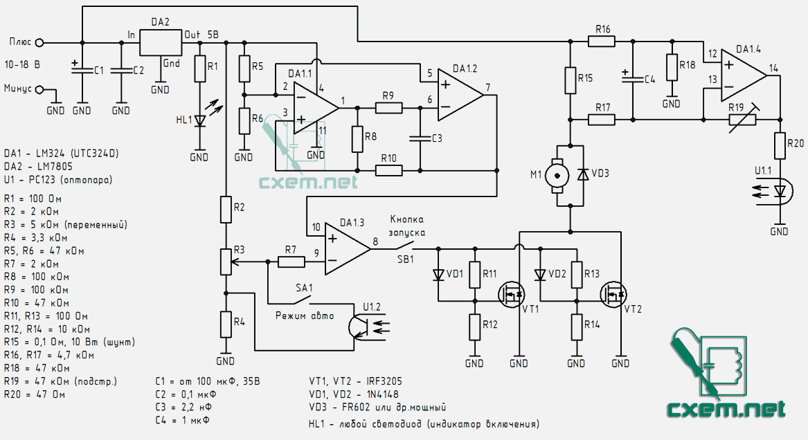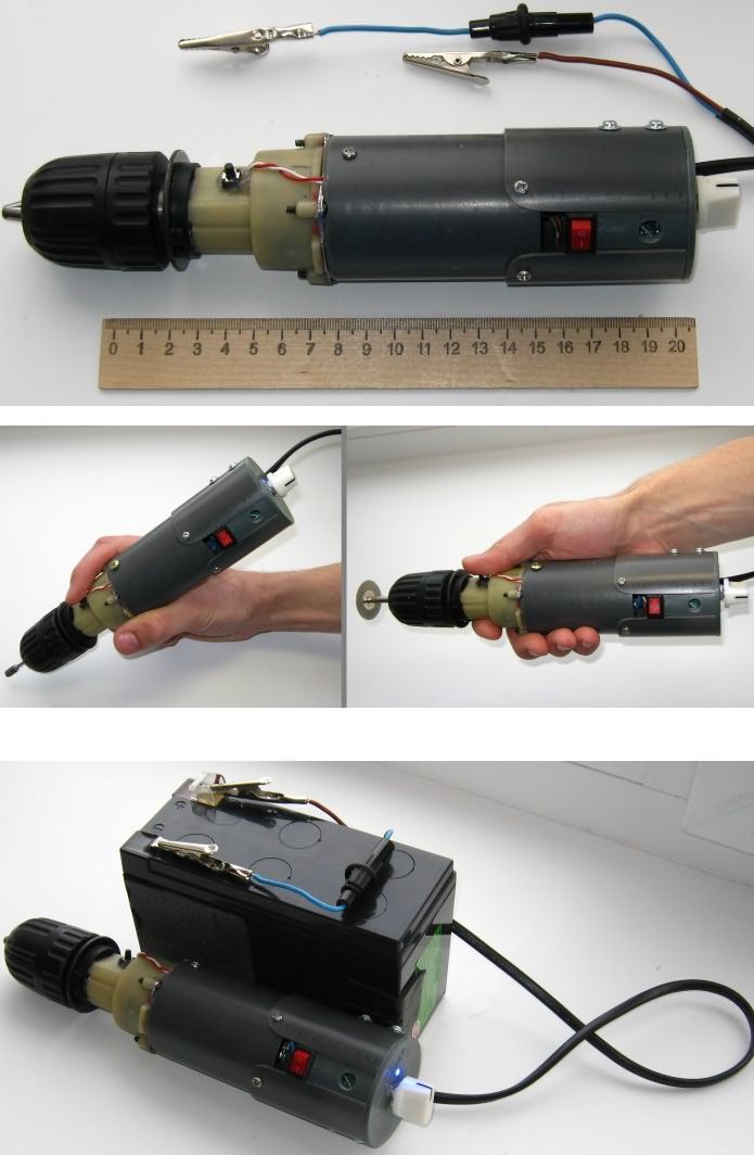
With mechanical modification and LM324 mosfet motor driver circuit, the battery has expired and the switch has been broken and the rechargeable drill has been converted into an engraving machine. There is a two-stage planetary gear box between the motor and the holder section, reducing the speed by 12 times. An arrangement has been made to increase the speed.
There are two MOSFETs connected in parallel in the LM324 controlled PWM motor driver power section and it heats up very little at high powers. It is also strongly recommended that the FR602 diode be placed parallel to the motor. It is stated that it not only provides protection against self-induction surges, but also strangely reduces heating. This diode was not used during the tests, as a result, the mosfets got very hot and many of them failed.
You may hear a squeak at low speeds because… The PWM frequency is in the audible range. It is not recommended to increase the frequency above 2-3 kHz. The mosfet transistors get very hot at high frequencies.

The fourth op-amp performs an additional function: automatic increase in speed. For example, imagine that you need to drill a hole in wood, plastic, a circuit board or any other material. When this is done with a screwdriver, drilling is usually started at a low rotation speed. When the drill is focused on the desired point, you can increase the pressure on the button and continue at high speeds.
To implement this function, it is necessary to monitor the changes in the current consumed by the motor. For this purpose, the circuit includes a shunt R15. This is a powerful low-resistance resistor through which the current from the source is fed to the motor. The resistance of this resistor is very low, only 0.1 Ohm, and the losses are negligible. The current passing through the shunt creates a voltage drop across the shunt. In idle mode, it is about 0.2 volts. This voltage is amplified many times by the fourth op-amp.
The amplified signal comes out at pin 14 and controls the PC123 optocoupler. They are separated in the diagram and marked as U1.1, U1.2.
To enable this mode, you need to close the SA1 switch. Thus, the LED lights up, opening the phototransistor and shorting the middle terminal of the potentiometer with the extreme terminal. The duty cycle of the PWM signal decreases sharply and the speed increases.

Şifre-Pass: 320volt.com
source: cxem.net/master/121.php