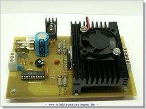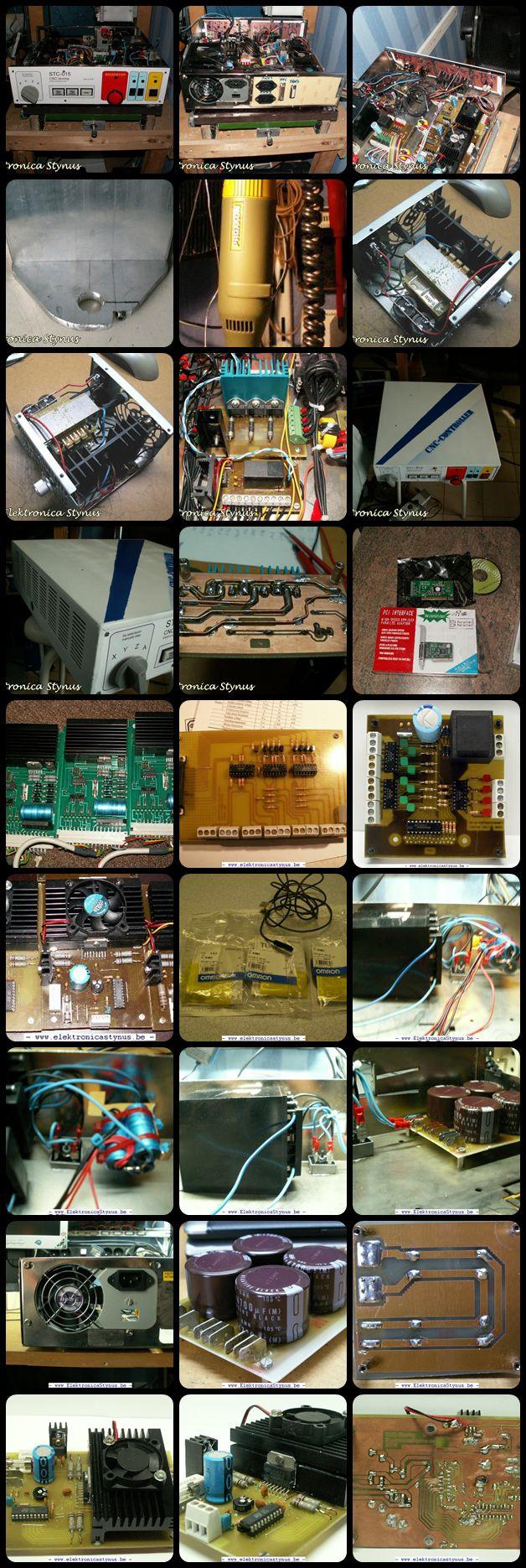
Motor driver board for CNC Machine L297, L298 author conducted with integrated 3 axis control circuit for each engine used. LPT parallel port that communicates with the computer is done via the ULN2803 circuit and built on PC849 opto
For controlling the motors I’m using a chopper controller that works with L297 and L298 ic. The components therefor I’m going to pick up a few control print I received (see below). Rik The reason that I do not use print as they are is because if you adhere to a stepper motor that immediately begins to turn and the steering is not really universal.
CNC Circuit Test

Source: “http://www.elektronicastynus.be/Projecten/CNC/Elektronica.php” CNC Milling Drive Control Circuits alternative link:
Şifre-Pass: 320volt.com
Published: 2010/03/08 Tags: motor control circuit, motor driver circuit
Handmade Coil Transformer Winding Machine
Once so I thought was an issue SMPS transformer to wrap a simple mechanism how the board would say they engaged in this business to the machines spinning wheel trying to do was hard 🙂 get ready for some research I did after my curiosity went past a few documents at the scene of As I wanted to share, maybe the winder who want to make our readers who may be knows, maybe I can do it 🙂
Top of assembly. The base timber is a piece of laminated plywood. Angles are two pieces of junk (they were a tower, are galvanized to fire). drive shafts are printer, easily findable in any junk computer that fixes printers. The good thing is that these axles are steel, but it is not a very hard steel. Can you easily work with it.
Handmade Coil Winder