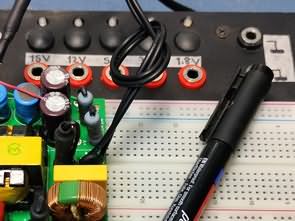
Regulator, Power Supply I have completed the power supply, which is the second phase of the Big Breadboard project, and boxed it up. It could have been all together under the breadboard plate, but this is fine as it is, it was a very long project anyway, no need to bother anymore, it works.
Power Supply Design and SMPS Integrated Use
The power supply is a SMPS (Switch Mode Power Supply) type and is controlled by an IR2153 integrated circuit. The power transformer is an EI28 model removed from an old generation ATX power supply. Although the original circuit is 300W, since my project does not require high power, components such as capacitor values, transformer and cooler were selected accordingly.
SMPS Grounding and Other Details
The video also covers the grounding details of the SMPS and other important information.


TL431 Mosfet Regulator Circuit
In the SMPS Circuit, I reduced the +25V output to 15 volts with the Mosfet regulator and gave it to the LM7812 input.

The circuit consists of a powerful mosfet (Q1) connected to the positive line and a reference voltage source mounted on the TL431. The output voltage is set by a divider consisting of R2, R3 and R4. The output voltage is calculated by the following formula:
VOUT = VREF × (1+R2/R4) – VGS
VREF: reference voltage TL431 – 2.5 V;
VGS: gate-source threshold voltage (1…2 V).
The Mosfet Transistor should be mounted on a heat sink with a surface area comparable to the power dissipation calculated using the following formula
Pq = (VIN – VOUT) x ILOAD,
Pq: transistor power dissipation.
VIN, VOUT: input and output voltages.
ILOAD: load current.
Mosfet TL431 Regulator Features:
Supply voltage: 6…50VDC
Output voltage: 3…27VDC
Maximum output current: 10A.
Note: If the load is inductive (motor, heater), a diode must be connected parallel to the load to dampen the reverse emissions. Additional capacitors (output) are connected according to the load at a rate of 1000μF per 1A load current. *If the filter capacitors of the input source are selected at a value suitable for the load current, there is no need to connect an additional capacitor to the input.
The maximum power dissipated by the Mosfet Transistor should not exceed 50W. The device does not have short circuit protection and if the load current or power loss value is exceeded, the Q1 Mosfet transistor may fail.
I am also adding the description of the Source 300W High Power IR2153 SMPS circuit, in addition, a short circuit protection that leads to full cut-off has been added in the second version of the circuit. The power transformer is wound on a 31x19x15 PC40 toroid core.
Toroid transformer winding: First, 1 layer of paper tape is wrapped around the core, then 52 turns of the primary winding is wound from 0.75 mm wire. Then, 1 layer of paper tape is wound. For the secondary winding, 11 turns are wound with 4 wires of 0.75 mm, then they are separated into two and combined.

IR2153 300W SMPS (Soft start + Short circuit protection)
300W SMPS Features:
Supply voltage: 210-240V
Output voltage (idle): +38/-38V
Power: 300W
Soft start: yes. (10ms)
Short circuit protection: yes.
The working principle of the protection is very simple, from the output of LO IR2153, it gives a square wave with amplitude of 12V and frequency of 44kHz through capacitor C11 and gate resistor R8, this signal turns the mosfet on and off. When the current through shunt R10 exceeds 7A even for a moment, capacitor C13 will charge, the 2N5551 transistor will open, and discharge the internal capacitance of the mosfet and capacitor C11.
The IRF740 Mosfet transistor will be closed and will only be able to open with the next signal from IR2153. The current through the Mosfet will be in the form of a sharp needle (similar to low pulse filling PWM). At 6A the pulses are normal. At a current of more than 7A the pulses take the form shown in the circuit diagram.


The new version also added R17 and transistor VT4 is the current sensor, VT1 and VT3 are triggers, In case of overcurrent or short circuit, when VT2 is triggered, IR2153 CT pin is pulled to chassis, SMPS is closed
ATTENTION The circuit works with high voltage, be careful, pay attention to capacitor connections, if you connect + – polarities in reverse, there may be big explosions at high voltage, use Fused Power Line, protective glasses before operating the circuit
Source: darkamp.ru/nadezhnyy-iip-na-ir2153/
Şifre-Pass: 320volt.com
Publication date: 2025/03/03 Tags: power electronic projects, smps projects