I gave the device in the Breadboard Box project that I shared before to my friend as a gift. He loves electronics (especially analog electronics) and since he makes lots of circuits, the Breadboard power supply system was very useful for him. I continued as before for a while. Finally, I finished my new big breadboard + power supply project.
I designed the Multi-output regulator card that I had in mind before. I exaggerated as I always do when I started 🙂 In the first version, I said that I would give a separate, suitable voltage to the input of each regulator and thus get full power and efficiency. I designed the PCB accordingly.
I used thick cables and then I came to my senses as if we were making a high power industrial system 🙂 You haven’t needed high current in breadboard circuits for years, you are testing with different methods at high powers anyway, I said stop 🙂
Again, like in the old breadboard box, I connected the LM7812 12V output to the LM7805 integrated circuit, and the 5V output is 3.3V 1.8V to the regulator. I used the Ethernet cable wire instead of thick cables, the thickness of this wire is more than enough.
A PCB board was used to cool the LM317, LM337, LM7812, LM7805, LM1117-3.3 and LM1117-1.8 regulator integrated circuits, there is not much space on the top but the bottom part is completely copper, as I said, since high power is not required, the heat will not be too much, I also mounted the card on a thick piece of aluminum (24X16cm) and used small coolers for the upgrade.
Breadboard Regulator Board Circuit Diagram

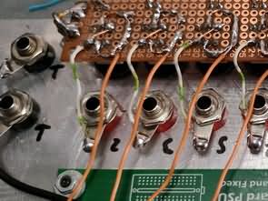
One of the sections I struggled with the most was the on-off switches. The tiny switches were very suitable, but it was difficult to process aluminum, I had to make a hole and then grind or file it to give it a rectangular shape, there are no small varieties of push-release switches with nuts and easy to install, they are all large.
I used a 6 pin 8×8 push-release switch. What I was wondering about with this switch was the current value to be drawn from it, every seller gave different values for the same button, 300mA, 500mA, 1A, 1.5a etc. I said I couldn’t trust these, I tore 1 switch apart as if it could carry 1 ampere according to the metal thickness, and since the switch was double, I increased the power by making a parallel connection.
I used a perforated plate for the assembly of the switches, I also mounted the indicator LEDs, it looked nice and was easy to use. I had to leave a space for the plastic piece I attached to the button head to look neat and not to stay on top, I solved that too, but I had to make the coolers I used for the upgrade 2X, although the height was not too much, but this was not in the calculation
I sanded the aluminum plate well before painting, then washed it with soapy water, applied the paint, after it dried, I heated it with a hot air gun (180 degrees) to make it stick better (it was written in the user manual..)
The final state of the large breadboard, breadboard box project is like this. The regulator card was tested, no problem. I was thinking of writing the outputs and adjustment pots with a white eding pen, but I couldn’t find a fine-tipped eding pen, I think it would be more original if I had made the panel design and printed foil, but I was able to finish it quickly with long breaks, this state is good.
I will share the power supply in the second part.


Note: PCB Design was made with Sprint layout 6, dimensions are 10x10cm. If you want to make any edits, close the “C2” layer from the bottom section for a clearer view.
Şifre-Pass: 320volt.com
Publication date: 2025/03/03 Tags: power electronic projects, power supply project