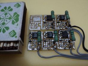
Battery balancer circuit is designed to control the charge thresholds of LifePO4 and Li-ion batteries. You can use it on Li-ion and LifePO4 batteries by changing 2 resistor values on the balancer.
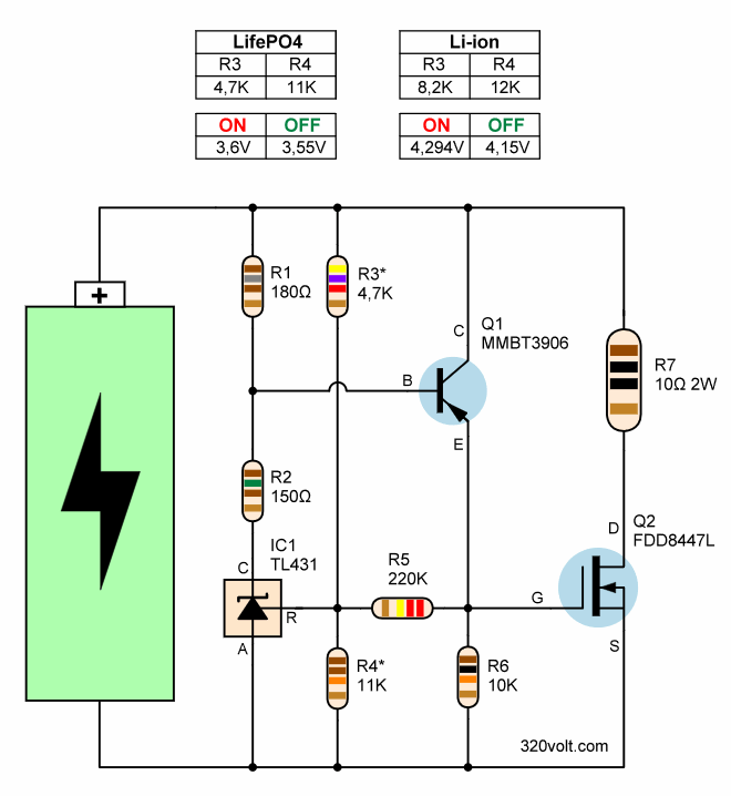
By adding transistor T1 and resistor R5 to the circuit, it was possible to convert TL431 into a Schmitt trigger. The divider R3, R4 determines the threshold of the controlled voltage. When the voltage at the control electrode reaches 2.5 Volts, transistor TL431 and Q1 open.
In this case, the collector potential increases and part of this voltage enters the TL431 control electrode circuit through resistor R5. The circuit achieves significant hysteresis. Switching on occurs at 3.6 Volts (for LifePO4 battery) and shutdown occurs at 3.55 Volts.
In this case, a very steep-edged control pulse occurs at the gate of the mosfet transistor and the power transistor cannot enter active mode. In the circuit where the current passing through the balancing resistor is equal to 0.365 Amperes, the voltage drop in the drain-source connection is only 5-6 mV. At the same time, the mosfet transistor heats up very little.
The voltage divider can be configured for different voltage by changing the resistor values R3, R4. The maximum balancing current is determined by resistor R7.
Balancing voltages for the LiFePO4 battery are in the range of 3.6V to 3.7 Volts (the maximum allowable voltage for LiFePO4 is 3.75 Volts). During assembly, ordinary 5% tolerance resistors were used. Despite this, good results were obtained. I think R3 and R4 resistor tolerances should be at least 1%
LifePO4 Li-ion Battery Balancer Circuit Diagram

Source cxem.net/pitanie/5-295.php
Şifre-Pass: 320volt.com
Publication date: 2024/03/16 Tags: power electronic projects