
Many projects are usually carried out with a single battery. serial battery connection is required for higher voltages if the charger does not have balancing, deterioration occurs according to the capacity of the batteries, the batteries that are loaded early are overloaded and deteriorated, and this problematic battery, the charging circuit for charging the batteries prematurely finishes charging before the other batteries are charged. For example; We need 12V in our project 3 Li-ion batteries in series with full charge 1 battery voltage 4.2V in this case 12.6V charger for 3 batteries needed We have started to charge our batteries and each battery has a different capacity and occupancy rate Some batteries have an early filling the middle battery in the schematic reaches the limit value of 4.2V and the others are not fully charged in this case the total voltage will not stop charging until the 12.2V charge cycle is 12.6V.
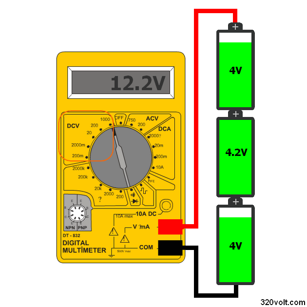
After charging, the battery will exceed the middle battery limit voltage. 4.4V will be charged. The other batteries are not fully charged. They are left at 4.1V but the total voltage is 12.6V.
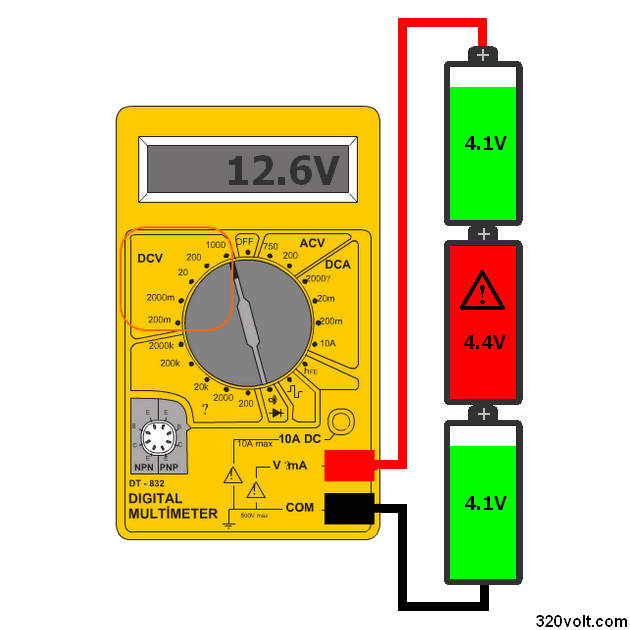
We use our batteries when we charge them with a charger that does not have a new balancing circuit. Depending on the condition of the battery, the battery will be charged much faster and will be charging in the same way.
The battery balance circuit </ strong> detects the premature battery charge in order to prevent this situation and usually uses resistance as the load. In this case, the battery voltage does not exceed the limit value.
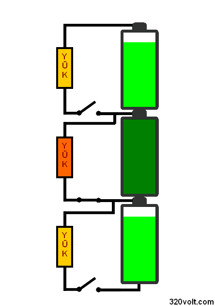
Simple Battery Balancing Circuit
Some of the most frequently used circuits are transistors with simple structure. Some use direct transistor load. Some of them use diode, load resistor, diode. In the following circuit, BD140 PNP is used as transistor load. TL431 REF can be precise voltage adjustment with trimpot connected to the foot.
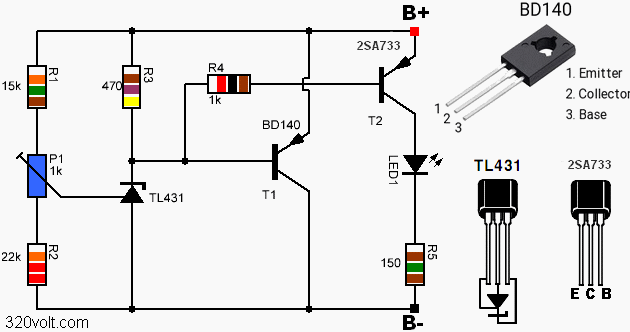
There is no need to use this circuit for a single battery. One of the balance circuits is used for each battery in the serial connection Three serial Li-ion battery connection schemes for 12.6V;
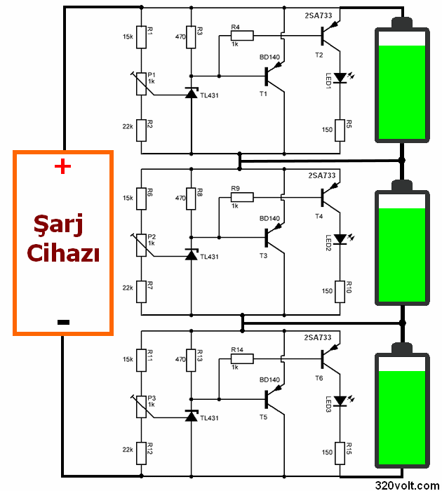
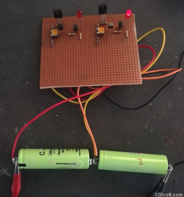
For the circuit testing, we can think of the dimensions as perforated platelet lead test purposes, which can be done in much smaller sizes with regular PCB drawing and SMD materials.
Set up the battery balance circuit: First, set the voltage of your set power source to 4.25V. Set the 1K trimmer slowly until it starts emitting light ( or TL431 REF with 2.5V at the foot. ), the current drawn from the power supply is a value between 100mA and 400mA according to the power of the battery. I use 300mA for the 18650 Li-ion battery
Basically TL431 REF should be resistance setting as 2.5V in the foot, if you use full value resistor you do not need trimpot but easiest is to use multi-turn timpot
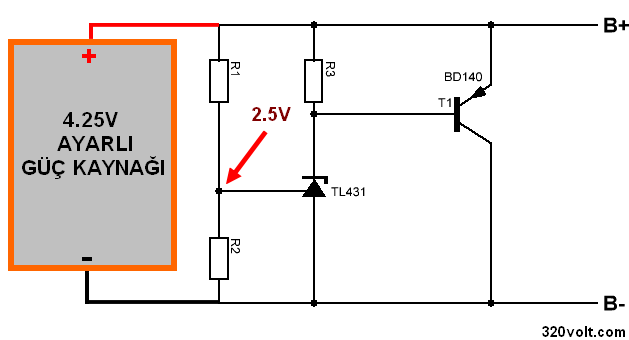
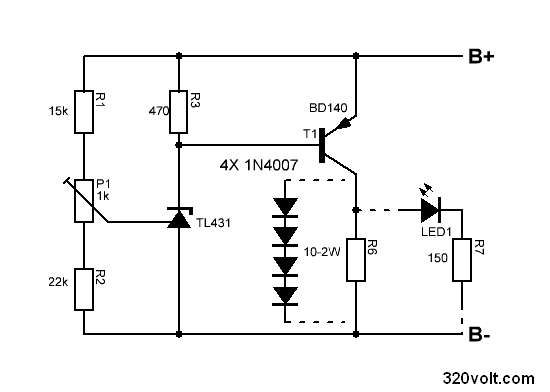
In this circuit, the direct BD140 transistor is used as the load. In some applications, 1W … 2W 5 …. 10-OHM resistor or series 3 … 4 1N4007 diodes are connected to the PNP transistor collector façade. I did not use it in the tests, but if you use the BD140 transistors with a 1K trimmer you need to connect a small cooler, you can make more precise adjustments, and the voltage divider 15K, 22K resistors are better than 1% tolerances.
Publication date: 2018/06/09 Tags: power electronic projects
Auswuchten von Li-Ionen-Li-Polymer-Batterien Batterie-Auswuchtschaltung
Viele Projekte werden normalerweise mit einer einzigen Batterie durchgeführt. Bei höheren Spannungen ist ein serieller Batterieanschluss erforderlich, wenn das Ladegerät nicht ausbalanciert ist, eine Verschlechterung der Kapazität der Batterien auftritt, die Batterien, die früh geladen werden, überlastet und beschädigt sind, und diese problematische Batterie, die Ladeschaltung für das vorzeitige Laden der Batterien beendet das Laden, bevor die anderen Batterien geladen werden.
Beispielsweise; Wir benötigen 12V in unserem Projekt 3 Li-Ionen-Batterien in Serie mit voller Ladung 1 Batteriespannung 4.2V in diesem Fall 12.6V Ladegerät für 3 Batterien benötigt Wir haben begonnen, unsere Batterien aufzuladen und jede Batterie hat eine andere Kapazität und Auslastung Einige Batterien Haben Sie eine frühe Füllung der mittleren Batterie im Schaltplan erreicht den Grenzwert von 4,2 V und die anderen sind nicht vollständig geladen in diesem Fall die gesamte Spannung wird nicht aufhören aufzuladen, bis der 12,2 V Ladezyklus ist 12,6 V.
Automatic Feeding Machine With CD-ROM Mechanic
Automatic Feeding Machine With CD-ROM Mechanic
For the author, the automatic feeding machine for the wedge is the easiest mechanical part for the application. they insert a plastic container all of which is placed on the CD present on the CD-ROM and put the ready-made cat here. Attiny13 Automatic feeding circuit A simple driver circuit is used for engine control based on the Attiny13 microcontroller. The operating voltage of the feeding circuit is 9v Attiny13 supply 78L05 regulator provided with the project’s proteus simulation scheme, source codevision avr c, hex code files are available.
When the over voltage is applied, the D2 LED flashes. By pressing the button briefly, the sled opening time can be selected as 12, 24, 36, 48 hours. The time setting is indicated by led: 12 hours, 2 times 24, 3 times – 36, led light without pause. Pressing the button for a long time, if necessary, opens or closes the rails. This does not affect the Timing setting.
Timer ready modules are sold more easily to control the application. This circuit can be done by using CD-ROM mechanism with different circuit, devices and automatic feeding system.
Automatic Feeding Circuit Schematic
Circuit d’équilibrage de la batterie des batteries Li-ion Li-Polymer
De nombreux projets sont généralement réalisés avec une seule batterie. la connexion de la batterie série est requise pour les tensions plus élevées si le chargeur n’a pas d’équilibrage, la détérioration se produit en fonction de la capacité des batteries, les batteries qui sont chargées tôt sont surchargées et détériorées, et cette batterie problématique, le circuit de charge pour charger les batteries prématurément termine la charge avant que les autres batteries soient chargées. Par exemple; Nous avons besoin de 12 V dans notre projet 3 batteries Li-ion en série avec charge complète 1 tension de batterie 4,2 V dans ce cas Chargeur 12,6 V pour 3 batteries nécessaires Nous avons commencé à charger nos batteries et chaque batterie a une capacité et un taux d’occupation différents Certaines batteries avoir un remplissage précoce de la batterie du milieu dans le schéma atteint la valeur limite de 4,2 V et les autres ne sont pas complètement chargés dans ce cas, la tension totale n’arrêtera pas de charger jusqu’à ce que le cycle de charge de 12,2 V soit de 12,6 V.
can i use the battery without removing it from the circuit?
Hi, not recommended. Much more advanced systems are used for this. BQ series ICs
Guten Tag, die Schaltung funktioniert perfekt bei 4,2V.
Welchen Teilungswiederstand benötige ich für 3,50V.
Bitte höflich um Information.
MfG
Binder
Hi, You can adjust it with the trimpot.
Danke für die Info. Ich habe den Spannungsteiler angepasst, da ich meine Lifepoe4 bei ca. 3,45V halten möchte.
Mir ist aufgefallen dass das balancen bei 3,38V beginnt und bei 3,55V die volle Leistung hat.
Wie könnte ich das ganze ändern, damit die Regelung zwischen 3,38V und 3,45V folgt.
Was kann man an der Schaltung ändern?
Bitte höflich um Info.
MfG
Alpin28
Replace the r1 or r2 resistor with a trimpot and adjust it.
Ich habe heute schon Versuche mit sämtlichen widerständen getestet, ich glaube kaum, dass da ein Potentiometer was ändern wird?!
Was wäre, wenn ich am R3 was ändere?
MfG
Alpin28
Fehler habe ich gefunden.
Die Kabel vom Multimeter zum Strom messen waren etwas zu dünn!
Da ich die Schaltung mit drei Keramikwiderstände verwende, fließen ca. 1,7A und das ist nicht wenig.
Danke noch einmal für die super Schaltung!!!!!!
Genau so etwas habe ich für meine Lifepoe4 Batterien gesucht.
MfG
Alpin28
Ich freue mich über Ihren Erfolg.
ich habe die kabel gewechselt 🙂
Es gibt ein Mosfet-Design für Lifepoe4-Batterien. balancer-mosfet-lifepo4-lion.zip pass. 320volt.com
Mit freundlichen Grüßen